New Semester
Started
Get
50% OFF
Study Help!
--h --m --s
Claim Now
Question Answers
Textbooks
Find textbooks, questions and answers
Oops, something went wrong!
Change your search query and then try again
S
Books
FREE
Study Help
Expert Questions
Accounting
General Management
Mathematics
Finance
Organizational Behaviour
Law
Physics
Operating System
Management Leadership
Sociology
Programming
Marketing
Database
Computer Network
Economics
Textbooks Solutions
Accounting
Managerial Accounting
Management Leadership
Cost Accounting
Statistics
Business Law
Corporate Finance
Finance
Economics
Auditing
Tutors
Online Tutors
Find a Tutor
Hire a Tutor
Become a Tutor
AI Tutor
AI Study Planner
NEW
Sell Books
Search
Search
Sign In
Register
study help
engineering
introduction to electrical power
Introduction To Electrical Power And Power Electronics 1st Edition Mukund R. Patel - Solutions
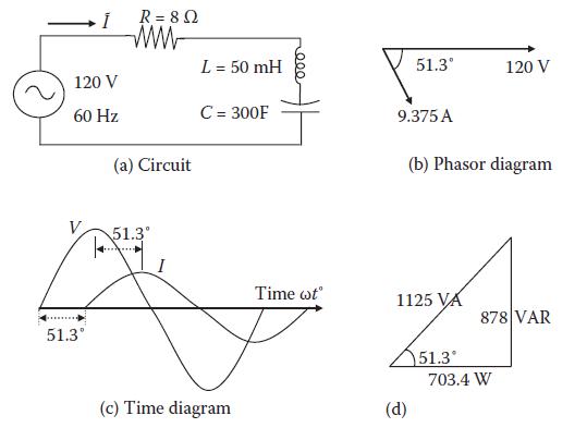
Determine the current and power in the following circuit, and draw the phasor and time diagrams. İ 120 V 60 Hz 51.3° R = 8 Ω www (a) Circuit 51.3° I L = 50 mH C = 300F (c) Time diagram 000 Time wt 51.3° 9.375 A (d) 1125 VA (b) Phasor diagram 51.3° 120 V 878 VAR 703.4 W
Why should the plant power engineer use power at or near a unity power factor as much as possible?
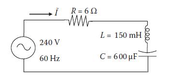
For the circuit shown below, determine the current and power and draw the phasor and time diagrams. Ï 240 V 60 Hz R = 60 ww L = 150 mH C= 600 μF-
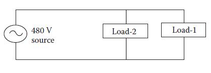
Two parallel loads draw power from a 480-V source as shown in the figure below, where Load-1 draws 15 kW and 10 kVAR lagging, and Load-2 draws 7 kW and 5 kVAR leading. Determine the combined pf and the total kVA drawn from the source. 480 V source Load-2 Load-1
Draw a set of balanced three-phase currents in a Y-connected system with neutral wire, and graphically, using the tip-tail method, find their sum Ĩa + Ĩb + Ĩc = Ĩn returning via the neutral wire.
Three parallel loads draw power from a 480-V source. Load-1 is 25 kW and 15 kVAR lagging, load-2 is 10 kW and 8 kVAR leading, and load-3 is 18 kW and 10 kVAR lagging. Determine the combined power factor and the total kVA drawn from the source.
In a balanced three-phase Y-connected power circuit, why does the circuit behave exactly the same with or without the neutral wire? What purpose does the neutral wire, where provided, serve in a three-phase four-wire system?
A Y-connected generator has the line-to-neutral voltage phasor Ṽan= 100 ∠ 0. Determine the line-to-line voltage phasors Ṽab, Ṽbc, and Ṽca with their phase angles with respect to Ṽan.
A Δ-connected transformer has the line-to-line voltage phasor Ṽab= 480 ∠0. Determine the line-to-neutral voltage phasors Ṽan, Ṽbn, and Ṽcn in magnitudes and phase angles with respect to Ṽab.
A balanced Δ-connected load-1 has ZLL1 = 6 + j9 Ω in each phase of Δ. It is connected in parallel with a balanced Y-connected load-2 with ZLN2 = 2 + j3 Ω in each phase of Y. If these two parallel loads are powered by a three-phase, Y-connected generator with a 480-V line voltage, determine the
A balanced Y-connected load-1 has ZLN1 = 4 + j1 Ω in each phase of Y. It is connected in parallel with a balanced Δ-connected load-2 with ZLL2 = 12 + j6 Ω in each phase of Δ. If these two parallel loads are powered by a three-phase, Y-connected generator with a 480-V line voltage, determine
Determine the average and rms values of a square wave current of +10 A for t = 0 to 2.5 ms and –10 A for t = 2.5 to 5 ms.
Determine the average and rms values of a rectangular wave current of +5 A for 0 to 2 ms and –5 A for t = 2 to 6 ms.
Powered by a 120-V rms voltage source, three impedances are connected in parallel: (i) 10 + j20 Ω, (ii) 5 + j20 Ω, and (iii) 10 + j30 Ω. Determine the real power drawn by each impedance. Without making numerical calculations, how would you have identified the impedance that will draw the highest
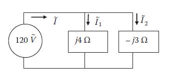
In the circuit shown below, determine Ĩ, Ĩ1, and Ĩ2, and draw the phasor diagram, taking 120 V as the reference phasor. 120 V ↓Ĩ₁ 4 Ω ↓1₂ -j3 Ω
A 120-V source is connected to a load impedance of 31.8 + j42.4 Ω. Determine(a) The load current, (b) Complex power, (c) Real power, (d) Reactive power, and (e) Apparent power. Be sure to include with each answer the phase angle and the unit as applicable.
A three-phase, 440-V, 60-Hz load draws 30-kW real power and 40 kVAR reactive power from the source: (i) determine the line current, complex power, and apparent power drawn from the source; (ii) draw the power triangle; and (iii) if the reactive power is reduced to 10 kVAR, keeping the same real
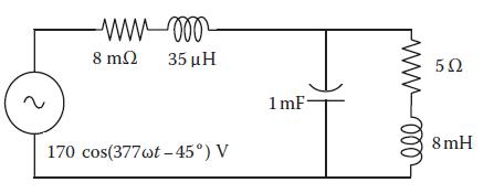
The circuit in the figure below is shown in time domain. First, convert it into the phasor domain showing the voltage and impedance as phasors, and then find the total impedance and current drawn from the source. M-0002 8 ΜΩ 35 ΜΗ 170 cos(377wt –45°) V 1mF- 1000 5Ω 8mH
A 440-V, three-phase, Y-connected generator delivers power to a Δ-connected load with 6 + j9 Ω in each phase of Δ. Determine the line current and three-phase power to the load.
A three-phase Δ-connected load has 4.5 + j6.3 Ω impedance in each phase of Δ. For easy circuit calculations with other parallel loads connected in Y, the Δ-load needs to be converted into an equivalent Y. Determine the impedance Z in each phase of the equivalent Y.
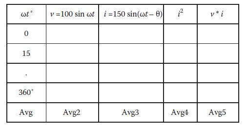
Prepare an EXCEL spreadsheet as shown in the table below for one cycle of 60-Hz ac in the increments of 15°. With θ = 0°, plot the voltage, current, and power versus ωt using the CHART function in EXCEL. Find the average values of columns 2 through 5. Then, verify that (a) The square root of
Determine the rms value of voltage induced in an 80-turn coil on a 30 × 25 cm cross-section core with peak flux density 1.7 T alternating at 60 Hz.
Two parallel single-phase rectangular bus bars 2 cm apart at center lines experience 30,000 Arms current when a load gets short-circuit fault. Determine the peak mechanical force per meter length of the bus bars. Assume the bus bar shape factor K = 0.85.
Using Faraday’s law, explain why we lose radio and cell phone communications while going through a long tunnel made of steel-reinforced concrete structure.
A transformer has no-load loss of 30 kW and full-load loss of 90 kW when delivering 3-MW power. Determine its (1) full load efficiency and (2) maximum efficiency with the corresponding loading level in percentage of the full load and in kilowatts.
Using Faraday’s law, explain the purpose of the front door screen in the microwave oven.
If a dc source with open circuit voltage of 240 V drops to 220 V under a 25-A load, determine its Thevenin parameters, that is, the source voltage Vs and the source resistance Rs.
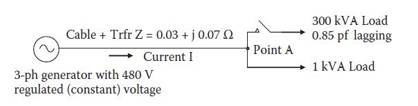
From a three-phase, 480-V generator switchboard, a feeder takes three phase power to two equipment's at the other end—similar to the figure in Example 2.5—via cable and transformer with the combined series impedance Z = 0.04 + j0.09 Ω/phase. The voltage at the receiving end point A rises and
A dc source with open circuit voltage of 120 V drops to 105 V under a 15-A load. Determine its Thevenin parameters, that is, the source voltage Vs and the source resistance Rs.
How would the magnetic loss in a 60-Hz motor built in the United States change when operated in Europe at 50 Hz, and vice versa?
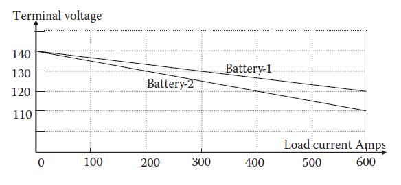
Two batteries’ terminal voltage versus load current droop lines are shown in the figure below. Determine analytically the load current shared by each battery and the battery bus voltage if they share a total load current of (1) 500 A and (2) 800 A. In case of a 500-A total load, verify your
State in one sentence when the electrical equipment operates at the maximum efficiency.
How would you determine the Thevenin equivalent source parameters Vs and Zs of the entire power grid bringing power to the wall outlet at your workplace? Answer separately assuming that (1) the source reactance is negligible, that is, Zs = Rs (a pure resistance), and (2) the source reactance is not
An electrical equipment is designed for 25-year life with 70°C rise in 40°C ambient air at a rated load. If it is continuously overloaded by 10%, determine its new expected life.
You have two 120-V batteries working in parallel, one old and one new, each with 60 cells in series. You wish the new battery to share greater load. What would you do?
A 500-hp, 460-V motor winding insulation resistance was measured to be 15 MΩ when sitting idle in normal room temperature of 25°C. Determine whether this motor is worthy of continuing service as per the IEEE Standard.
In a long locomotive going uphill with two engines pulling, how would you determine their horsepower load-sharing to meet the total traction load?
A 75-kVA, single-phase, 60-Hz transformer primary coil with 100 turns is connected to a 265-V source. Determine the peak flux in the core. If the magnetomotive force of 500 ampere-turns is needed to establish this flux, determine the core excitation current.
At what rate does the electrical equipment’s service life degrade at higher operating temperature? Identify specific reasons of the life degradation.
A feeder transformer delivers full load current at its output voltage of 460 V. When the load is removed, the output voltage rises to 480 V. Determine the voltage regulation of this transformer.
A generator winding delivering rated load of 1000 kVA rises to 50°C above 40°C ambient air, making its operating temperature 40 + 50 = 90°C. If the generator is overloaded by 30%, determine its operating temperature. If always operated at 30% overload, determine the generator life if the rated
A 4160-V generator phase coil insulation resistance is 20 MΩ measured at 70°C soon after it was tripped. Compare this with the minimum required by the industry standard, and state whether this generator is good to continue in operation.
A single-phase, 500-kVA, 440/120-V transformer feeds service loads via bus duct with two bus bars, each 1/2 × 3 in. in cross section and spaced ½ in. apart. An electrical system study has concluded that the worst-case fault current in the bus is 30,000 A at the first peak. Determine the peak
A power electronics component designed to last 25 years under rated load is always operated 5°C above the design temperature limit. Determine its expected life if 8°C rule for one-half life is found to be applicable to electronics components.
A 1000-kVA, single-phase transformer operating at 85% power factor lagging at a full rated load has conductor power loss of 10 kW and core loss of 5 kW. Determine its maximum possible efficiency and the corresponding load level as percentage of the rated load.
A three-phase, 460-V, Y-connected generator is powering a 500-kW balance three-phase Δ-connected load at 0.85 pf lagging. Determine (1) The line-to-line voltage and line current, (2) The generator phase voltage and phase current, and (3) The load phase voltage and phase current.
A three-phase, Y-connected, 480-V generator is powering 1000-kW balanced three-phase Δ-connected load at 0.90 pf lagging. Determine (1) the line-to-line voltage and line current, (2) the generator phase voltage and phase current, and (3) the load phase voltage and phase current.
Explain the difference between electrical degree and the mechanical degree in rotating electrical machines.
A balanced Y-connected load with 3 + j5 Ω/ph (L-N) is connected in parallel with a balanced Δ-connected load with 12 + j15 Ω/ph (L-L). Determine the combined total equivalent Y-connected impedance per phase. If these loads were powered by a Y-connected 2400 VLL generator, determine the current
A balanced Y-connected load with 2 + j3 Ω/ph (L-N) is connected in parallel with a balanced Δ-connected load with 9 + j12 Ω/ph (L-L). Determine the combined total equivalent Y-connected impedance value per phase. If these loads were powered by a Y-connected 480-VLL generator, determine the
List three reasons that may cause the generator to fail in building up the terminal voltage.
A 30-MVA, 11-kV, 60-Hz, three-phase, Y-connected synchronous generator has Xs = 2 Ω/ph and negligible Ra. Determine its power angle when delivering rated power at unity power factor.
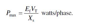
A three-phase, 11-kV, 60-Hz, 10-MVA, Y-connected synchronous generator has Xs = 1 Ω/ph and negligible Ra. Determine its power angle δ when delivering rated power at unity power factor. (First calculate Ẽf and Pmax.)
Explain the counter torque developed in the generator when the load is connected to the stator terminals.
A three-phase, Y-connected synchronous generator is rated 10 MVA, 11 kV. Its resistance is negligible, and the synchronous reactance is 1.5 Ω per phase. Determine the generator voltage Eg when delivering rated megavolt-amperes at 0.85 power factor lagging.
A three-phase, Y-connected synchronous generator is rated 15 MVA, 13.8 kV. Its resistance is negligible, and the synchronous reactance is 2 Ω per phase. Determine the field excitation voltage Ef when delivering rated megavolt-amperes at 0.90 power factor lagging.
Explain why the field excitation current of the generator alters the power factor as seen by the machine.
A 3-MVA, 60-Hz, 6.6-kV, four-pole, 96% efficient round rotor synchronous generator has the synchronous reactance of 4.0 Ω/phase and negligible armature resistance. When operating at unity power factor, determine (1) The maximum power it can deliver under steady state with no step loading, (2)
In light of Equation 3.6, discuss the generator maximum power capability at lower frequency all the way up to zero frequency (dc). At very low frequency, what would limit the maximum power capability?Equation 3.6 Pmax EVT X₂ watts/phase.
A 5-MVA, 60-Hz, 6.6-kV, four-pole, 95% efficient round rotor synchronous generator has the synchronous reactance of 7.0 Ω/phase and negligible armature resistance.When operating at unity power factor, determine (1) The maximum power it can deliverer under steady state (no step load changes), (2)
A large cruise ship generator was repaired and brought back online by synchronizing with five other generators, which collectively make an infinite bus for the incoming generator. The incoming generator has the synchronous reactance Xs = 1.2 pu, VT = 1.0 pu, and the field current If = 800 A at the
One of six generators on a large cruise ship was repaired and brought back online by synchronizing with other five generators, which in a group can be assumed to make an infinite bus for the incoming generator. The incoming generator has the synchronous reactance Xs = 1.5 pu, VT = 1.0 pu, and the
Explain the construction and performance differences between the round rotor and salient pole synchronous machines.
An 80-MVA, four-pole, 60-Hz synchronous generator operates at 0.90 power factor lagging. Its cylindrical rotor of 5-m length and 1.5-m diameter has the average mass density of 8.3 g/cm3. Assuming that the turbine rotor has inertia 1.5 × generator rotor inertia, determine the inertia constant H of
A 100-MVA, four-pole, 60-Hz synchronous generator that operates at 0.90 power factor load has a cylindrical rotor 5 m long and 1.5 m in diameter. The average mass density of the rotor’s copper and magnetic steel combined is 8 g/cm3. Determine the kinetic energy of the generator rotor running at
Identify two problems you may encounter in applying a large load in one step on a synchronous generator.
A 50-Hz round rotor generator has Ef = 1.4 pu, VT = 1.0 pu, Xd = 1.5 pu, and H = 7 s. Determine the mechanical natural frequency of the turbine–generator oscillations under a transient disturbance when operating at 80% load.
A 60-Hz round rotor generator has Ef = 1.5 pu, VT(bus) = 1.0 pu, Xd = 1.3 pu, and H = 5 s. Determine the mechanical natural frequency of the turbine–generator oscillations under transient disturbance when operating at 50% load.
What loading events in a steel mill may cause large step load on the standalone generator of the mill?
A 60-Hz synchronous generator rated 30 MVA at 0.90 power factor has the no-load frequency of 61 Hz. Determine (1) The prime mover speed regulation,(2) The GFR, and(3) The generator FDR.
A 60-Hz synchronous generator rated 100 MVA at 0.90 power factor has the no-load frequency of 61.5 Hz. Determine the prime mover speed regulation, the GFR, and the generator FDR.
What causes damping in the rotor oscillations following a sudden step change in the generator load?
The no-load frequency of two ac generators is the same, 61 Hz. The FDR of generator-1 is 0.001 Hz/kW, and that of generator-2 is 0.0005 Hz/kW. If the two generators are in parallel supplying a total load of 1000 kW, determine the load shared by each generator and the operating frequency of the bus.
The no-load frequency of two ac generators is the same, 60.5 Hz. The FDR of generator-1 is 0.0006 Hz/kW, and that of generator-2 is 0.0008 Hz/kW. If the two generators are in parallel supplying a total load of 1500 kW, determine the load shared by each generator and the operating frequency of the
In the synchronous machine, where the damper bars are located, what is their purpose, and how do they work?
A 1000-kVA, 460-V, 60-Hz, three-phase, four-pole generator has squirrel cage damper bars of 1-cm diameter on each of the rotor pole surface. What would be the damper bar current under the steady synchronous speed operation?
Two 40-MW, 60-Hz generators, one isosynchronous and one drooping, share an equal load of 25 MW each when supplying a total load of 50 MW with the bus frequency exactly at 60 Hz. If the total load is increased to 70 MW, determine the load on the isosynchronous generator and the bus frequency.
Two 60-Hz generators, one isosynchronous and one drooping, share 15 MW each when supplying a total load of 30 MW with the bus frequency exactly at 60 Hz. If the total load is increased to 40 MW, determine the load on the isosynchronous generator and the bus frequency.
Why can two generators at different voltage and frequency not work in parallel?
A 4160-V, 60-Hz, three-phase, Y-connected generator has a synchronous reactance of 0.9 pu and negligible armature resistance. At rated armature current, determine the field excitation current range for a power factor changing from zero lag to unity to zero lead. Express the range in terms of the
List the conditions that must be met before a synchronous generator can be paralleled with other generators or with the power grid.
A three-phase, 500-kVA, 480-V, 60-Hz, Y-connected synchronous generator gave these test results at rated speed:(1) Open circuit voltage at rated field current = 560 VLL (2) Short circuit current at rated field current = 305 A. When cold at 20°C, the average dc resistance of three armature phase
While transferring load from one generator to another, what changes really take place during this process in terms of the prime mover’s GSR settings and the droop lines? Which way the droop lines get adjusted and how do these changes transfer the load?
Clearly identify the benefits of using an isosynchronous generator. If two such generators are placed in parallel, what would you expect to happen?
Two generators are operating in parallel, one with a droop and the other isosynchronous. Explain their load sharing behavior when the total bus load increases and decreases.
If the synchronous generator suddenly gets shorted at its terminals, how would the speed change before the turbine fuel supply is reduced or cut off?
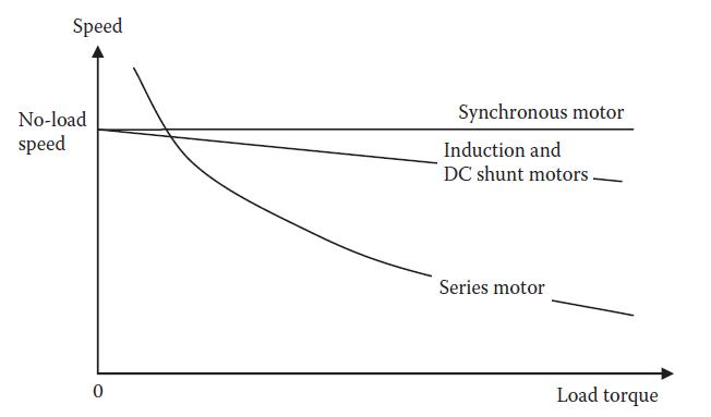
A two-pole, 60-Hz, three-phase, 3460-rpm induction motor runs at 3580 rpm at no load. Determine at rated load:(1) The slip speed in revolutions per minute, (2) The slip in per unit and percent, and(3) The speed regulation. Speed No-load speed 0 Synchronous motor Induction and DC shunt
A four-pole, 60-Hz, three-phase, 1740-rpm induction motor runs at 1790 rpm at no load. Determine at rated load:(1) The slip speed in revolutions per minute,(2) The slip in per unit and percentage, and(3) The speed regulation.
Discuss the principal difference in construction and operation of the induction motor and the synchronous motor.
A 60-Hz, three-phase, four-pole induction motor delivers full load torque at 3% slip. If the load torque rises by 20% (overload condition), determine the new speed.
A 75-hp, three-phase, six-pole, 60-Hz induction motor delivers full load torque at 5% slip. If the load torque is increased by 15% as allowed by the service factor on the nameplate, determine the new speed and horsepower delivered.
Which two factors jointly produce a rotating magnetic field in three-phase induction and synchronous motors?
A 100-hp, three-phase, 60-Hz, 460-V, four-pole, 1750-rpm induction motor is used in an application, which would load the motor to only 65% of the rated torque (this is obviously a higher-rated motor than we need). Determine:(1) Whether the motor at 65% load torque runs faster or slower than the
A 150-hp, three-phase, 60-Hz, 460-V, four-pole, 1750-rpm induction motor is used in an application that loads the motor to only 70% of the rated torque. Determine:(1) The actual speed and(2) The actual horsepower delivered to the load.
Why is the slip necessary for the operation of the induction motor?
A 100-hp, three-phase, 60-Hz, 460-V, 1710-rpm, four-pole, letter code J, squirrel cage induction motor with Δ-connected stator has efficiency of 90% and power factor 0.85 lagging when operating at rated load. Determine the input kilowatt, kilovolt-ampere, and line current during normal operation
A 125-hp, three-phase, 60-Hz, 460-V, four-pole, 1720-rpm, letter code M, squirrel cage induction motor with a Δ-connected stator has efficiency 92% and power factor 0.90 lagging when operating at rated load. Determine the input kilowatt, kilovolt-ampere, and line current during normal operation
At what speed would an ideal induction motor on frictionless bearings run in vacuum?
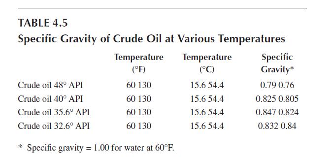
A 100-hp, three-phase, 460-V, 60-Hz, ac motor has a power factor of 0.90 lagging and efficiency of 94% on its nameplate. Determine the line current it will draw while delivering rated horsepower. TABLE 4.5 Specific Gravity of Crude Oil at Various Temperatures Crude oil 48° API Crude oil 40°
A 5000-hp, 60-Hz, 1200-rpm, 4.1-kV, three-phase, Y-connected overexcited synchronous motor draws the armature current of 800 A at 0.85 leading power factor under rated load. It has a synchronous reactance of 1.5 Ω/ph and negligible resistance. Determine (1) The counter emf Ẽf, (2) The torque
Showing 200 - 300
of 476
1
2
3
4
5
Step by Step Answers