New Semester
Started
Get
50% OFF
Study Help!
--h --m --s
Claim Now
Question Answers
Textbooks
Find textbooks, questions and answers
Oops, something went wrong!
Change your search query and then try again
S
Books
FREE
Study Help
Expert Questions
Accounting
General Management
Mathematics
Finance
Organizational Behaviour
Law
Physics
Operating System
Management Leadership
Sociology
Programming
Marketing
Database
Computer Network
Economics
Textbooks Solutions
Accounting
Managerial Accounting
Management Leadership
Cost Accounting
Statistics
Business Law
Corporate Finance
Finance
Economics
Auditing
Tutors
Online Tutors
Find a Tutor
Hire a Tutor
Become a Tutor
AI Tutor
AI Study Planner
NEW
Sell Books
Search
Search
Sign In
Register
study help
engineering
principles foundation engineering
Principles Of Foundation Engineering 9th Edition Braja M. Das, Nagaratnam Sivakugan - Solutions
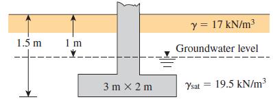
A column foundation (Figure P6.9) is 3 m × 2 m in plan. Given: Df = 1.5 m, ϕ' = 25°, c' = 70 kN/m2. Using Eq. (6.28) and FS = 3, determine the net allowable load [see Eq. (6.24)] the foundation could carry.Figure P6.9 Eq. (6.24)Eq. (6.28) y = 17 kN/m3 1.5 m 1 m Groundwater level 3 m x 2 m
A 2.0 m wide strip foundation is placed in sand at 1.0 m depth. The properties of the sand are: γ = 19.5 kN/m3, c' = 0, and ϕ' = 34°. Determine the maximum wall load that the foundation can carry, with a factor of safety of 3.0, usinga. Terzaghi’s original bearing capacity equation with his
Determine the maximum column load that can be applied on a 1.5 m × 1.5 m square foundation placed at a depth of 1.0 m within a soil, where γ = 19.0 kN/m3, c' = 10 kN/m2, and ϕ' = 24°. Allow a factor of safety of 3.0.
A 2.0 m wide continuous foundation carries a wall load of 350 kN/m in a clayey soil where γ = 19.0 kN/m3, c' = 5.0 kN/m2, and ϕ' = 238. The foundation depth is 1.5 m. Determine the factor of safety of this foundation using Eq. (6.28).Eq. (6.28) qu = c'N,FeFcaFeci + qN„FqsFqaFqi +
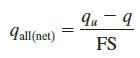
Use the general bearing capacity equation [Eq. (6.28)] to solve the following:a. Problem 6.1ab. Problem 6.1bc. Problem 6.1cEq. (6.28) qu = c'N,FeFcaFeci + qN„FqsFqaFqi + >yBN,F,„FyaFyi + ŻYBN,F,FydFy %3D cst cd' ci
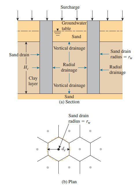
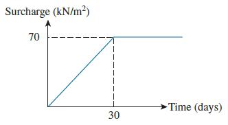
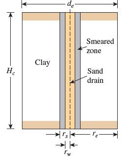
For a sand drain project (Figure 5.20), the following are given:Clay: Normally consolidatedHc = 5.5 m sone{way drainagedCc = 0.3eo = 0.76cv = 0.015 m2/dayEffective overburden pressure at the middle of clay layer = 80 kN/m2Sand drain: rw = 0.07 mrw = rsde = 2.5 mcv = cvrA surcharge is applied as
A 3.05-meter-thick clay layer is drained at the top and bottom. Its characteristics are cvr = cv (for vertical drainage) = 39.02 cm2/day, rw = 203 mm, and de 51.83 m. Estimate the degree of consolidation of the clay layer caused by the combination of vertical and radial drainage at t = 0.2, 0.4,
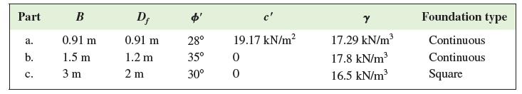
For the following cases, determine the allowable gross vertical load bearing capacity of the foundation. Use Terzaghi’s equation and assume general shear failure in soil. Use FS = 4. Part В D; c' Foundation type 0.91 m 0.91 m 28° 19.17 kN/m? 17.29 kN/m Continuous а. b. 1.5 m 1.2 m 35° 17.8
The diagram of a sand drain is shown in Figures 5.21 and 5.22. Given: rw = 0.25 m, rs = 0.35 m, de = 4.5 m, cv = cvr = 0.3 m2/month, kh/ks = 2, and Hc = 9 m. Determine:a. The degree of consolidation for the clay layer caused only by the sand drains after six months of surcharge applicationb. The
A 3.0 m thick singly drained normally consolidated clay layer has eo = 0.89, Cc = 0.46, and cv = 3.5 m2/year. The effective overburden pressure at the middle of the layer is 105.0 kN/m2. It is proposed to build a large warehouse that is expected to impose a pressure of 50.0 kN/m2 at the ground
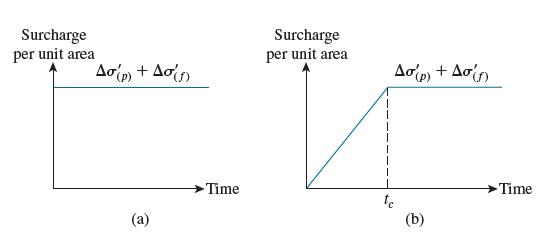
In Problem 5.8, the client sees the one-year duration of the preload as too long and wants to limit this to 6 months. What should the total surcharge be during this period?Problem 5.8A 5 m thick doubly drained normally consolidated clay layer at a site has eo = 0.95, Cc = 0.54, and cv = 4.0
A 5 m thick doubly drained normally consolidated clay layer at a site has eo = 0.95, Cc = 0.54, and cv = 4.0 m2/year. The effective overburden pressure at the middle of the clay layer is 70.0 kN/m2. Some proposed construction work is expected to impose a 60.0 kN/m2 load at the ground level.a.
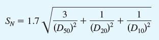
For the soil A, B, and C in Problem 2.7, find the suitability numbers using Eq. (5.17) and the suitability of these soil for densification using vibroflotation method. What are these soil?Eq. (5.17)Problem 2.7.Figure P2.7 shows the grain-size distribution of four soil A, B, C, and D. The plastic
For a vibroflotation work, the backfill to be used has the following characteristics:D50 = 2 mmD20 = 0.7 mmD10 = 0.65 mmDetermine the suitability number of the backfill. How would you rate the material?
The undisturbed soil at a given borrow pit is found to have the following properties: w = 15%; γ = 19.1 kN/m3; Gs = 2.70. The soil from this borrow is to be used to construct a rolled fill having a finished volume of 38,500 m3. The soil is excavated by means of a shovel and dumped onto trucks
Repeat Problem 5.3 using Osman et al. (2008) correlations.Problem 5.3.For a cohesive soil with LL = 45 and PL = 25, estimate the difference in the wopt and γd(max) values between standard and modified compaction tests. Use Gurtug and Sridharan (2004) correlations.
In a sandy soil, the maximum and minimum void ratios were determined to be 0.725 and 0.465, respectively. The specific gravity of the soil grains is 2.65.a. What would be the relative density of this sand compacted to a dry unit weight of 16.46 kN/m3?b. Assuming the maximum dry unit weight of the
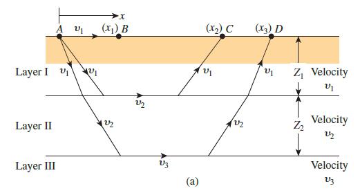
The results of a refraction survey (Figure 3.45a) at a site are given in the following table. Determine the thickness and the P-wave velocity of the materials encountered.Distance from the source of disturbance (m) ………….. Time of first arrival of P waves (s × 103)2.5
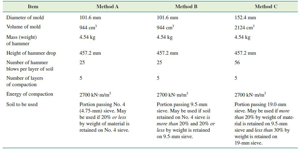
From the test specifications given in Table 5.2, show that the compactive energy in method C is 2700 kN ∙ m/m3.Table 5.2 Item Method A Method B Method C Diameter of mold 101.6 mm 101.6 mm 152.4 mm Volume of mold 944 cm 944 cm 2124 cm Mass (weight) 4.54 kg 4.54 kg 4.54 kg of hammer Height of
The P-wave velocity in a soil is 105 m/s. Assuming Poisson’s ratio to be 0.32, calculate the modulus of elasticity of the soil. Assume that the unit weight of soil is 18 kN/m3.
A dilatometer test was conducted in a clay deposit. The groundwater table was located at a depth of 3 m below the surface. At a depth of 8 m below the surface, the contact pressure (P0) was 280 kN/m2 and the expansion stress (p1) was 350 kN/m2. Determine the following:a. Coefficient of at-rest
In a pressuremeter test in a soft saturated clay, the measuring cell volume Vo = 535 cm3, po = 42.4 kN/m2, pf = 326.5 kN/m2, vo = 46 cm3, and vf = 180 cm3. Assuming Poisson’s ratio (µs) to be 0.5 and using Figure 3.31, calculate the pressuremeter modulus (Ep).
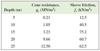
A piezocone test was carried out at a site, and the following readings were recorded for the cone resistance qc and sleeve friction fs. Determine the soil present at these depths. Cone resistance, Sleeve friction, Depth (m) I. (MN/m?) f, (kN/m?) 5 0.21 12.5 10 1.05 40.5 15 3.23 75.2 20 9.66 60.7 25
In a site consisting entirely of clays, an electric friction cone penetrometer measures the cone resistance qc at a depth of 8.0 m as 0.75 MN/m2. The water table is at 3.0 m below the ground level. The unit weights of the clay above and below the water table are 16.5 kN/m3 and 19.0 kN/m3,
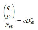
For the data given in Problem 3.22, if D50 = 0.8 mm, find the N60 values at each depth. Use Eq. (3.55) with Kulhawy and Mayne values for a and c.Eq. (3.55)Problem 3.22A cone penetration test was carried out in normally consolidated sand, for which the results are summarized below:Depth (m)
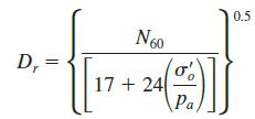
For the data given in Problem 3.22, determine the relative density at each depth using Eq. (3.51). Assume moderately compressible sand and hence Qc = 1.Eq. (3.51)Problem 3.22A cone penetration test was carried out in normally consolidated sand, for which the results are summarized below:Depth (m)
A cone penetration test was carried out in normally consolidated sand, for which the results are summarized below:Depth (m) ........................ Cone resistance, qc (MN/m2)2.0 ....................................................... 3.123.5 .......................................................
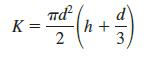
By considering the failure surfaces in a vane shear test, show from the first principles that, for a rectangular vane, TC K = h + 2
A vane shear test was conducted in a saturated soft clay, using a 100 mm x 200 mm vane. When the vane was rotated at the standard rate of 0.1°/s, the torque measured in the torque meter increased to 60 N ? m, and with further rotation reduced to 35 N ∙ m. Determine the peak and residual
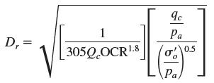
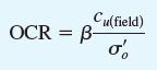
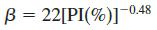
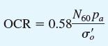
Refer to Problem 3.18. Determine the overconsolidation ratio for the clay. Use Eqs. (3.42) and (3.45). Use σ'o = 64.2 kN/m2.Eqs. (3.42)Eqs. (3.45)Problem 3.18.a. A vane shear test was conducted in a saturated clay. The height and diameter of the rectangular vane were 101.6 mm and 50.8 mm,
Refer to Problem 3.16. Estimate the overconsolidation ratio of the clay. Use Eqs. (3.42) and (3.43).Eqs. (3.42)Eqs. (3.43)Problem 3.16.Refer to Figure P3.3. Vane shear tests were conducted in the clay layer. The vane (tapered) dimensions were 63.5 mm (d) × 127 mm (h), iB = iT = 45° (see Figure
a. A vane shear test was conducted in a saturated clay. The height and diameter of the rectangular vane were 101.6 mm and 50.8 mm, respectively. During the test, the maximum torque applied was 280 N? m. Determine the undrained shear strength of the clay.b. The clay soil described in part (a) has a
Refer to Figure P3.3. Vane shear tests were conducted in the clay layer. The vane (tapered) dimensions were 63.5 mm (d) × 127 mm (h), iB = iT = 45° (see Figure 3.23). For the test at A, the torque required to cause failure was 51 N ∙ m.For the clay, given: liquid limit = 46 and plastic limit =
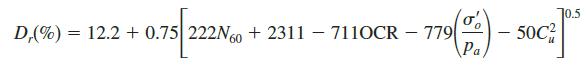
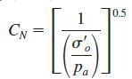
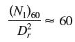
In a site consisting of normally consolidated clean sands, the water table is at 3.05 m depth. The average unit weight of the sand above and below the water table is 17.53 kN/m3 and 19.65 kN/m3, respectively. At a 7.62 m depth, N60 was reported as 26. Determine the following:a. (N1)60 using
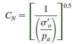
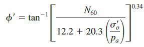
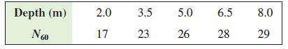
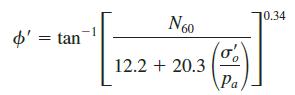
Standard penetration tests were carried out in sands where the N60 values at certain depths are reported as follows. The unit weight of the sand is 18.5 kN/m3. The water table is well below the test depths.Use Eq. (3.13) for CN. Determine the friction angle ϕ' using Eqs. (3.29), (3.30), and
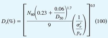
A standard penetration test was carried out in a normally consolidated sand at 7.62 m depth where the N60 was determined to be 28. The unit weight of the sand is 17.29 kN/m3, and the grain-size distribution suggests that D50 = 1.2 mm and Cu = 3.2. The age of the soil since deposition is
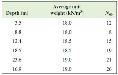
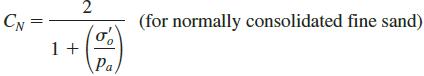
Standard penetration tests were carried out in normally consolidated fine sands at different locations. The following data were collected, with average unit weights assumed for the entire depth. Determine the (N1)60 values using the correction factors proposed by (a) Liao and Whitman (1986) and (b)
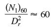
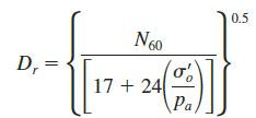
Refer to Problem 3.5. Using Eq. (3.28), determine the average relative density of the sand. Assume it is a fine sand. Use Eq. (3.13) to obtain (N1)60.Problem 3.5Following is the variation of the field standard penetration number (N60) in a sand deposit:Depth (m) .............. N601.5
Refer to Problem 3.5. Using Eq. (3.22), determine the average relative density of the sand.Problem 3.5Following is the variation of the field standard penetration number (N60) in a sand deposit:Depth (m) .............. N601.5 ............................. 63 ................................ 84.5
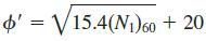
Repeat Problem 3.7 using Eq. (3.29). Use (N1)60 from Problem 3.5.Problem 3.7For the soil profile described in Problem 3.5, estimate an average peak soil friction angle. Use Eq. (3.31b).Problem 3.5Following is the variation of the field standard penetration number (N60) in a sand deposit:Depth (m)
Repeat Problem 3.7 using Eq. (3.30).Problem 3.7Following is the variation of the field standard penetration number (N60) in a sand deposit:Depth (m) .............. N601.5 ............................. 63 ................................ 84.5 ............................. 96
For the soil profile described in Problem 3.5, estimate an average peak soil friction angle. Use Eq. (3.31b).Problem 3.5Following is the variation of the field standard penetration number (N60) in a sand deposit:Depth (m) .............. N601.5 ............................. 63
Redo Problem 3.5 using Eq. (3.14).Problem 3.5Following is the variation of the field standard penetration number (N60) in a sand deposit:Depth (m) .............. N601.5 ............................. 63 ................................ 84.5 ............................. 96
Following is the variation of the field standard penetration number (N60) in a sand deposit:Depth (m) .............. N601.5 ............................. 63 ................................ 84.5 ............................. 96 ................................ 87.9 ........................... 139
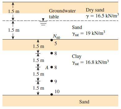
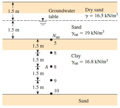
Refer to Figure P3.3. Use Eqs. (3.10) and (3.11) to determine the variation of OCR and preconsolidation pressure σ'c.Figure P3.3Eqs. (3.10)Eqs. (3.11) Dry sand y = 16.5 kN/m3 1.5 m Groundwater table Sand 1.5 m Ysat = 19 kN/m3 Ngo 60 5 1.5 m 8 Clay Ysat = 16.8 kN/m³ 1.5 m * A •8 1.5 m 1.5 m 10
A soil profile is shown in Figure P3.3 along with the standard penetration numbers in the clay layer. Use Eqs. (3.8b) and (3.9) to determine the variation of cu and OCR with depth. What is the average value of cu and OCR?Figure P3.3Eqs. (3.8b)Eqs. (3.9) Dry sand y = 16.5 kN/m3 1.5 m Groundwater
A thin-walled sampling tube must be fabricated to obtain good-quality undisturbed clay samples of 75 mm diameter. What is the maximum possible wall thickness?
A Shelby tube has outside diameter of 76.2 mm and wall thickness of 1.651 mm. What is the area ratio of the tube?
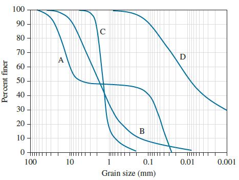
Estimate the friction angle of the soil C in Problem 2.7 (see Figure P2.7) at 80% relative density and void ratio of 0.61 using the empirical correlations given bya. Eq. (2.87)b. Eq. (2.88)Figure P2.7 100 90 80 70 A D 60 50 40 30 20 - B 10 TITII! 100 10 1 0.1 0.01 0.001 Grain size (mm) Percent finer
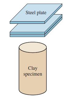
Steel plates with mass of 1500 g each were stacked on top of a 75 mm diameter and 150 mm high clay specimen, as shown in Figure P2.22. If the undrained shear strength of the specimen is 45.0 kN/m2, how many plates can be stacked before the specimen fails? What is the consistency term for this
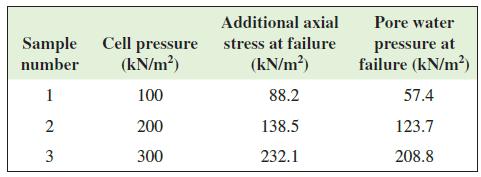
The data from a series of consolidated-undrained triaxial tests are summarized below. Draw the three Mohr circles, plot the failure envelope in terms of effective stresses, and find c' and f'. Additional axial Pore water Sample Cell pressure stress at failure (kN/m?) (kN/m?) pressure at failure
The specimens obtained from a clay layer at a site gave the following shear strength parameters from a consolidated-drained triaxial test: c' = 10 kN/m2 and ϕ' = 26°. A consolidated undrained triaxial test is carried out on this soil, where a specimen is consolidated under confining pressure of
A consolidated-drained triaxial test was carried out on a normally consolidated clay specimen, and the following results were recorded: σ'3 = 150 kN/m2 and Δσf = 260 kN/m2. An identical specimen from the same clay was subjected to a consolidated-undrained test with a confining pressure of 150
A consolidated-drained triaxial test is carried out on a sand specimen that is subjected to 100 kN/m2 confining pressure. The vertical deviator stress was increased slowly such that there is no build-up of pore water pressure within the specimen. The specimen failed when the additional axial stress
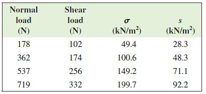
A direct shear test is conducted on a 60 mm x 60 mm overconsolidated clay specimen. The loading was very slow, ensuring that there is no pore water pressure development within the specimen (i.e., drained loading). The following data were recorded.Determine the shear strength parameters c9and f9.
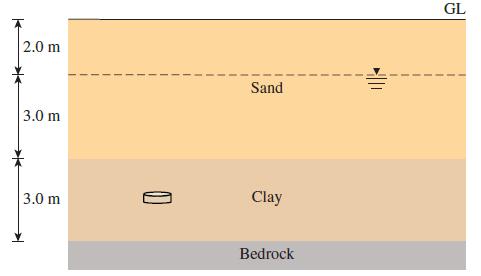
The soil profile at a site consists of a 2.0 m thick sand layer at the top, underlain by a 3.0 m thick clay layer. The water table lies at a depth of 1.0 m below the ground level. The bulk and saturated unit weights of the sand are 16.0 kN/m3 and 19.0 kN/m3, respectively. The properties of the
The soil profile at a site consists of 2 m of sand at the ground level, underlain by 6 m of clay, followed by a very stiff clay stratum that can be assumed to be impervious and incompressible. The water table is at 1.5 m below the ground level. The moist and saturated unit weights of the sand are
A clay layer with two-way drainage reached 75% consolidation in t years. How long would it take for the same clay to consolidate 75% if it has one way drainage?
The soil profile at a site is shown in Figure P2.13. The moist and saturated unit weights of the sand are 17.0 kN/m3 and 20.0 kN/m3, respectively. A soil specimen was taken from the middle of the clay layer and subjected to a consolidation test, and the following properties are reported:Natural
In a normally consolidated clay specimen, the following data are given from the laboratory consolidation test.e1 = 1.10 s91 = 65.0 kN/m2e2 = 0.85 s92 = 240.0 kN/m2a. Find the compression index Cc.b. What will be the void ratio when the next pressure increment raises the pressure to 460.0 kN/m2?
The depth of water in a lake is 4 m. The soil at the bottom of the lake consists of sandy clay. The water content of the soil was determined to be 25.0%. The specific gravity of the soil grains is 2.70. Determine the void ratio and the unit weight of the soil. What would be the total stress,
The soil profile at a site consists of 10 m of gravelly sand underlain by a soft clay layer. The water table lies 1 m below the ground level. The moist and saturated unit weights of the gravelly sand are 17.0 kN/m3 and 20.0 kN/m3, respectively. Due to some ongoing construction work, it is proposed
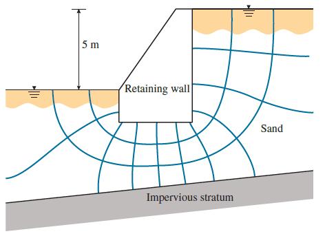
Seepage takes place around a retaining wall shown in Figure P2.9. The hydraulic conductivity of the sand is 1.5 x 10⁻³ cm/s. The retaining wall is 50 m long. Determine the quantity of seepage across the entire wall per day.Figure P2.9. 5 m Retaining wall Sand Impervious stratum
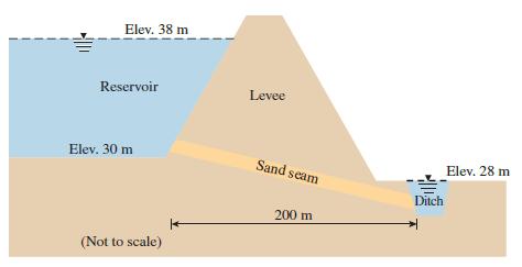
A 500 m long levee made of compacted clay impounds water in a reservoir as shown in Figure P2.8. There is a 1 m thick (measured in the direction perpendicular to the seam) sand seam continuing along the entire length of the levee, at 10° inclination to the horizontal, which connects the reservoir
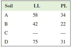
Figure P2.7 shows the grain-size distribution of four soil A, B, C, and D. The plastic limit and liquid limit of the fines are as follows.Describe the four soil and give their USCS symbols.Figure P2.7 Soil LL PL A 58 34 42 22 D 75 31
In AASHTO, which group are the following soil likely to fall into?a. A well-graded gravel with approximately 10% finesb. A well-graded sand with approximately 10% finesc. A uniform fine sandd. A high plastic clay
A granular soil with Gs = 2.65, emax = 0.870, and emin = 0.515 is compacted to a moist unit weight of 17.36 kN/m3 at moisture content of 10.5%. What is the relative density of this compacted sand?
The soil at a borrow area is at moisture content of 8.5% and unit weight of 17.5 kN/m3. This soil is used in the construction of a compacted road base where the dry unit weight is 19.5 kN/m3 and the moisture content is 14.0%. If the finished volume of the road base is 120,000 m3, what would be the
The top 500 mm of a site consists of a clayey sand with void ratio of 0.90 and water content of 20.0%. The specific gravity of the soil grains is 2.68. When the ground is compacted at the same water content, there is 45 mm reduction in the thickness of this layer. Determine the new void ratio and
The bulk density of a compacted soil specimen (Gs = 2.70) and its water content are 2060 kg/m3 and 15.3%, respectively. If the specimen is soaked in a bucket of water for several days until it is fully saturated, what should the saturated density be?
A large piece of dry rock has a mass of 2450 kg and volume of 0.925 m3. The specific gravity of the rock mineral is 2.80. Determine the porosity of the rock.
Showing 200 - 300
of 271
1
2
3
Step by Step Answers