New Semester
Started
Get
50% OFF
Study Help!
--h --m --s
Claim Now
Question Answers
Textbooks
Find textbooks, questions and answers
Oops, something went wrong!
Change your search query and then try again
S
Books
FREE
Study Help
Expert Questions
Accounting
General Management
Mathematics
Finance
Organizational Behaviour
Law
Physics
Operating System
Management Leadership
Sociology
Programming
Marketing
Database
Computer Network
Economics
Textbooks Solutions
Accounting
Managerial Accounting
Management Leadership
Cost Accounting
Statistics
Business Law
Corporate Finance
Finance
Economics
Auditing
Tutors
Online Tutors
Find a Tutor
Hire a Tutor
Become a Tutor
AI Tutor
AI Study Planner
NEW
Sell Books
Search
Search
Sign In
Register
study help
engineering
principles foundation engineering
Principles Of Foundation Engineering 9th Edition Braja M. Das, Nagaratnam Sivakugan - Solutions
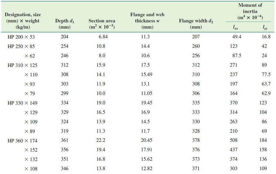
A steel pile (H-section; HP 310 × 125; see Table 12.1a) is driven into a layer of sandstone. The length of the pile is 25 m. Following are the properties of the sandstone: unconfined compression strength = qu(lab) = 80 MN/m2 and angle of friction = 36°. Using a factor of safety of 3, estimate the
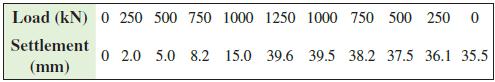
A 20 m long bored concrete pile having a diameter of 350 mm is load tested, and the data are given below: Also given: Econcrete = 25 × 103 MN/m2.a. Estimate the allowable pile load using Davisson’s (1973) method, with FS = 2.5.b. At the maximum load of 1250 kN, what are the total and
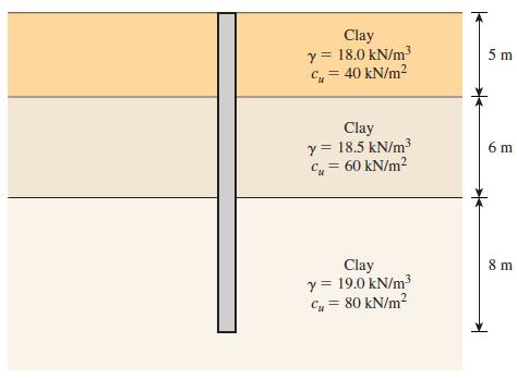
The average values of the undrained shear strength (cu) with depth are given as follows:Depth (m) ……………. cu (kN/m2)0–3 …………………………….. 203–8 …………………………….. 358–12 ……………………………. 8012–16 …………………………….
Consider a continuous flight auger pile in a sandy soil deposit 10 m long with a diameter of 0.45 m. Following is the variation of standard penetration resistance values (N60) with depth.Depth (m) ................................... N601.5 ................................................... 63.0
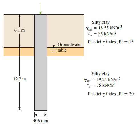
Solve Problem 12.13 using Eq. (12.58).Problem 12.13A concrete pile 406 mm × 406 mm in cross section is shown in Figure P12.13. Calculate the ultimate skin friction resistance by using thea. α method [use Eq. (12.61) and Table 12.11]b. λ methodc. β methodUse ϕ'R = 20° for all clays, which are
Solve Problem 12.13 using Eqs. (12.59) and (12.60).Problem 12.13A concrete pile 406 mm × 406 mm in cross section is shown in Figure P12.13. Calculate the ultimate skin friction resistance by using thea. α method [use Eq. (12.61) and Table 12.11]b. λ methodc. β methodUse ϕ'R = 20° for all
A concrete pile 20 m long having a cross section of 0.46 m × 0.46 m is fully embedded in a saturated clay layer. For the clay, given: γsat = 18 kN/m3, ϕ = 0, and cu = 80 kN/m2.Determine the allowable load that the pile can carry (FS = 3). Use the l method to estimate the skin resistance.
A concrete pile 406 mm × 406 mm in cross section is shown in Figure P12.13. Calculate the ultimate skin friction resistance by using thea. α method [use Eq. (12.61) and Table 12.11]b. λ methodc. β methodUse ϕ'R = 20° for all clays, which are normally consolidated.Table 12.11Variation of a
Redo Problem 12.10 using the l method for estimating the skin friction and Meyerhof’s method for the point load estimation.Problem 12.10A concrete pile 15.24 m long having a cross section of 406 mm × 406 mm is fully embedded in a saturated clay layer for which gsat = 19.02 kN/m3, ϕ = 0, and cu
A concrete pile 15.24 m long having a cross section of 406 mm × 406 mm is fully embedded in a saturated clay layer for which gsat = 19.02 kN/m3, ϕ = 0, and cu = 76.7 kN/m2. Determine the allowable load that the pile can carry. (Let FS = 3.) Use the α method Eq. (12.61) and Table 12.11 to
Determine the maximum load that can be allowed on the 450 mm diameter pile shown in Figure P12.9, with a factor of safety of 3. Use the a method and Table 12.11 for determining the skin friction and Eq. (12.20) for determining the point load.Figure P12.9Table 12.11Variation of a (InterpolatedValues
A 400 mm × 400 mm square precast concrete pile of 15 m length is driven into a sand where γ = 18.0 kN/m3 and ϕ' = 33°. Assuming δ' = 0.7ϕ' and K = 1.4 Ko, determine the load-carrying capacity of the pile with a factor of safety of 3. Use Meyerhof’s method [Eq. (12.18)] for computing the
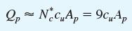
Redo Problem 12.3 using Coyle and Castello’s methods for estimating both Qp and Qs.Problem 12.3A 500 mm diameter and 20 m long concrete pile is driven into a sand where γ = 18.5 kN/m3 and ϕ' = 32°. Assuming δ' = 0.7ϕ' and K = 1.5 Ko, determine the loadcarrying capacity of the pile, with a
Consider a 500 mm diameter pile having a length of 18 m in a clay. Given: γ = 20.0 kN/m3 and cu = 60 kN/m2.a. Determine the maximum allowable load (Qall) with FS = 3. Use the a method and Table 12.11 for determining the skin friction and Eq. (12.20) for determining the point load. Allow a factor
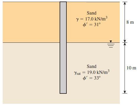
Determine the maximum load that can be allowed on a 450 mm diameter driven pile shown in Figure P12.6, allowing a factor of safety of 3. Use K = 1.5 Ko and δ' = 0.65ϕ' in computing the shaft load. Use Meyerhof’s method for computing the point load.Figure P12.6 Sand y = 17.0 kN/m d' = 31° 8 m
A 500 mm diameter and 20 m long concrete pile is driven into a sand where γ = 18.5 kN/m3 and ϕ' = 32°. Assuming δ' = 0.7ϕ' and K = 1.5 Ko, determine the loadcarrying capacity of the pile, with a factor of safety of 3. Use Meyerhof’s method [Eq. (12.18)] for computing the point load carrying
Repeat Problem 11.1 based on LRFD using the following factors:load factor for dead load = 1.25load factor for live load = 1.75strength reduction factor on the ultimate bearing capacity = 0.50Problem 11.1A continuous foundation is required in a soil where c' = 10 kN/m2, ϕ' = 26°, and γ = 19.0
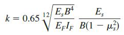
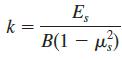
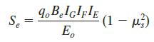
For a 2.0 m wide and 0.40 m thick beam on elastic foundation, determine the coefficient of subgrade reaction k using Eqs. (10.45) and (10.46), assuming the following parameters: Es = 30 MN/m2, EF = 30,000 MN/m2, ms = 0.25.Eqs. (10.45)Eqs. (10.46) E,B EFIF B(1 - u) E, k = 0.65. %3D
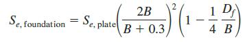
A 300 mm × 450 mm plate was used in carrying out a plate loading test in a sand, where the plate settled 5 mm under the applied pressure of 250 kN/m2.a. What is the coefficient of subgrade reaction for a 300 mm wide square plate?b. What would be the coefficient of subgrade reaction of a 2 m × 3 m
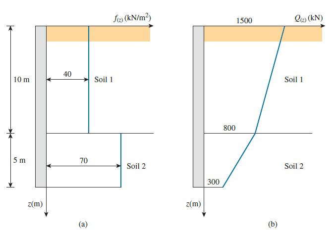
A 1500 kN load was applied on two 20 m long and 500 mm diameter piles that were instrumented for measuring the load variation with depth.a. The variation of frictional resistance per unit area, f(z), with depth for the first pile is shown in Figure P12.1a.Using Eq. (12.9), draw the variation of
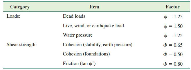
Repeat Problem 11.1 based on limit state design, using the factors given in Table 11.4.Table 11.4.Problem 11.1A continuous foundation is required in a soil where c' = 10 kN/m2, ϕ' = 26°, and γ = 19.0 kN/m3. The depth of the footing will be 1.0 m. The dead load and the live load are 600 kN/m and
A continuous foundation is required in a soil where c' = 10 kN/m2, ϕ' = 26°, and γ = 19.0 kN/m3. The depth of the footing will be 1.0 m. The dead load and the live load are 600 kN/m and 400 kN/m, respectively. Determine the required width for the foundation based on allowable stress design with
A plate loading test was carried out on a medium dense sand, using a 300 mm wide square plate, and k0.3 was determined as 100 MN/m3. Determine the coefficient of subgrade reaction for a 2.5 m wide square foundation and a 2.5 m × 3.5 m rectangular foundation.
In Problem 10.7, determine the consolidation settlement under the corner of the mat.Problem 10.7A 15 m × 20 m mat foundation shown in Figure P10.7 carries a building load of 36 MN and is placed at 3.0 m depth below the ground level.a. Find the net applied pressure on the underlying ground. The
A 2 m wide square foundation is placed at a depth of 1.5 m, in a very thick homogeneous sand deposit where qc = 10 MN/m2 and λ = 18.5 kN/m3. The stress level at the foundation is 140 kN/m2. Estimate the settlement in 25 years, using the method of Schmertmann et al. [Eq. (9.30)]. How much of this
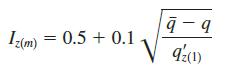
Refer to Figure 9.23. For a foundation on a layer of sand, given: B = 1.52 m, L = 3.05 m, d = 1.52 m, β = 26.6°, e = 0.152 m, and δ = 10°. The pressuremeter testing at the site produced a mean pressuremeter curve for which the pp(m) versus ΔR/Ro points are as follows.DR/Ro (1)
A 15 m × 20 m mat foundation shown in Figure P10.7 carries a building load of 36 MN and is placed at 3.0 m depth below the ground level.a. Find the net applied pressure on the underlying ground. The consolidation tests show that the preconsolidation pressure at the middle of the clay layer is 210
A dilatometer test was conducted in a sand deposit at a depth of 6 m. The groundwater table was located at a depth of 2 m below the ground surface. Given, for the sand: γd = 14.5 kN/m3 and γsat = 19.8 kN/m3. The contact stress during the test was 260 kN/m2. Estimate the soil friction angle,
It is proposed to build a 8 story building with a footprint of 15 m × 20 m, resting on a mat foundation of the same dimensions, in a saturated clay where cu = 50 kN/m2, γ = 19.0 kN/m3. Assume approximately 15 kN/m2 per floor for the live and dead loads.a. At what depth would you place the mat to
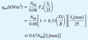
A 12 m × 9 m mat foundation is placed at a depth of 3 m within sand where N60 is 20. Using Eq. (10.14), estimate the elastic settlement when the net applied pressure is 250 kN/m2.Eqs. (10.14) Se Inet(kN/m?) N60 Fa 0.08 25, S(mm) 1+ 0.33 0.08 25
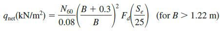
A 10 m × 6 m mat foundation is placed at 2.0 m depth in sand where the average value of N60 is 23. Determine the allowable net pressure that would limit the settlement to 75 mm, using Eqs. (9.47) and (10.14).Eqs. (9.47)Eqs. (10.14) N60 (B + 0.3 F 25 Inet (kN/m²) (for B > 1.22 m) 0.08 В
A 10 m × 8 m mat foundation is to be placed at 3 m depth in a saturated clay where cu = 60 kN/m2 and ϕ = 0. Determine the net ultimate bearing capacity.
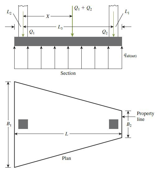
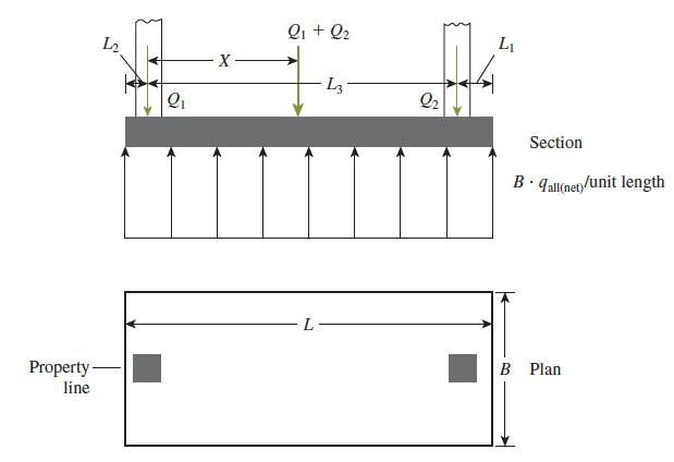
Refer to the trapezoidal combined footing in Figure 10.2, with Q1 = 1000 kN and Q2 = 500 kN. The distance between the columns L3 is 4 m, and the net allowable soil pressure is 125 kN/m2. It is required to maintain L2 as 1.5 m and L1 as 1 m. Determine the values for B1 and B2.Figure 10.2 |Q1 + Q2 L2
Refer to the rectangular combined footing in Figure 10.1, with Q1 = 500 kN and Q2 = 750 kN. The distance between the two column loads, L3 = 4.5 m. The proximity of the property line at the left edge requires that L2 = 1 m. The net allowable soil pressure is 120 kN/m2. Determine the breadth and
A 3.0 m wide square foundation is placed at 1.5 m depth in sand where γ = 18.5 kN/m3. The water table lies well below the foundation level. Under the applied pressure of 200 kN/m2 at the foundation level, the settlement recorded was 14.0 mm. It is expected that the water table will rise in the
A 2 m × 2 m foundation carrying a 1000 kN column load is placed at 1.0 m below the ground level in a sand where γ = 19 kN/m3 and (N1)60 = 25. Estimate the settlement using the Berardi and Lancellotta method (1991) (Section 9.7). Assume µs = 0.15.
A 2 m wide continuous foundation carrying a 260 kN/m wall load is placed at a depth of 1.0 m in sand where the unit weight is 19.0 kN/m3 and (N1)60 is 32. Assuming Poisson’s ratio of 0.15, estimate the settlement of the foundation. Use the procedure outlined in Section 9.7.
A shallow foundation measuring 1 m × 2 m in plan is to be constructed over a normally consolidated sand layer. Given: Df = 1 m, N60 increases with depth, N60 (in the depth of stress influence) = 12, and qnet = 153 kN/m2. Estimate the elastic settlement using Burland and Burbidge’s method
It is proposed to place a 3 m × 3 m foundation at 2 m depth in a sandy soil, where the average N60 is 25 and the unit weight is 18 kN/m3. Using Meyerhof’s expressions presented in Section 9.6, estimate the allowable net pressure that would give 30 mm of settlement.
Find the settlement of a 2.0 m wide square foundation (Df = 1.0 m) applying a net pressure of 150 kN/m2 to the underlying sand, where N60 = 20 and λ = 18.5 kN/m3.Use Eq. (9.43). In the last term of the equation, replace 1/4 by 1/3 (Leonards, 1986).Eq. (9.43) 2B Se, plate B + 0.3, 1 D 1 4 B Se
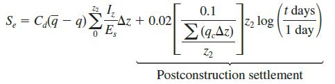
Solve Problem 9.10 using Eqs. (9.39), (9.40), and (9.41).Problem 9.10A continuous foundation on a deposit of sand layer is shown in Figure P9.10 along with the variation of the cone penetration resistance qc. Assuming λ = 18 kN/m3 and creep is at the end of ten years after construction, calculate
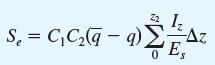
A continuous foundation on a deposit of sand layer is shown in Figure P9.10 along with the variation of the cone penetration resistance qc. Assuming λ = 18 kN/m3 and creep is at the end of ten years after construction, calculate the elastic settlement of the foundation using the strain influence
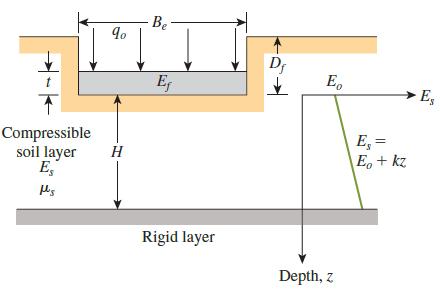
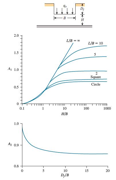
A plan calls for a square foundation measuring 3 m × 3 m supported by a layer of sand (see Figure 9.7). Let Df = 1.5 m, t = 0.25 m, Eo = 16,000 kN/m2, k = 400 kN/m2/m, ms = 0.3, H = 20 m, Ef = 15 × 106 kN/m2, and qo = 150 kN/m2. Calculate the elastic settlement. Use Eq. (9.27).Eq. (9.27)
Refer to Figure 9.7. Estimate the elastic settlement of the foundation in sand for the following data using the method of Mayne and Poulos [Eq. (9.27)].Foundation: length L = 3 m, width B = 2 m, depth Df = 1 m, thickness t = 0.25 m, Ef = 25 × 103 MN/m2Loading: net applied pressure qo = 125
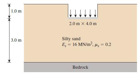
A 2.0 m × 4.0 m flexible loaded area shown in Figure P9.6 applies a uniform pressure of 150 kN/m2 to the underlying silty sand. Estimate the elastic settlement below the center of the foundation.Figure P9.6 1.0 m 2.0 m x 4.0 m Silty sand E, = 16 MN/m2, u, = 0.2 3.0 m Bedrock
Redo Problem 9.4 with Df = 1.0 m.Problem 9.4A 2 m × 4 m flexible foundation is placed on a granular soil with Df 5 0. The foundation applies a pressure qo = 120 kN/m2. Assuming the soil mass to be infinitely thick, with Es = 15 MN/m2 and µs = 0.1, determine the expected settlement beneath
Redo Problem 9.3 for the situation where the same soil is underlain by bedrock at 3.0 m below the surface.Problem 9.3A 2 m × 4 m flexible foundation is placed on a granular soil with Df 5 0. The foundation applies a pressure qo = 120 kN/m2. Assuming the soil mass to be infinitely thick, with Es =
A 2 m × 4 m flexible foundation is placed on a granular soil with Df 5 0. The foundation applies a pressure qo = 120 kN/m2. Assuming the soil mass to be infinitely thick, with Es = 15 MN/m2 and µs = 0.1, determine the expected settlement beneath the center of the foundation.
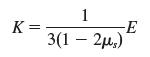
For an elastic material, the bulk modulus (K) and Young’s modulus (E) are related byFor undrained loading, deduce that µs = 0.5. 1 K = 3(1 - 2р.,)
Refer to Figure 9.1, where a 2.0 m × 3.0 m flexible foundation is placed in a saturated clay at 1.5 m depth. Bedrock lies at 4.0 m below the foundation. The clay is overconsolidated with OCR = 2, undrained shear strength = 60 kN/m2, and plasticity index = 45. If the pressure applied by the
A 2-m diameter flexible foundation applies a uniform pressure to the underlying soil of 200 kN/m2. Plot the variation of the vertical stress increase below the center of the foundation as determined using both the Boussinesq (ΔσB) and Westergaard (ΔσW) solutions up to a depth of z = 5 m. (µs =
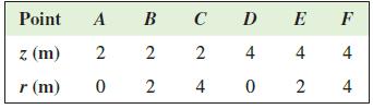
A point load of 500 kN is applied on an elastic medium with Poisson’s ratio of 0.2. Compare the vertical stress increase at the following locations as determined by the Boussinesq (ΔσB) and Westergaard (ΔσW) solutions. Point A B C D E F z (m) 2 4 4 4 r (m) 4 2. 4. 2.
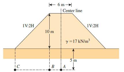
Figure P.8.12 shows an embankment load on a silty clay soil layer. Determine the stress increase at points A, B, and C, which are located at a depth of 5 m below the ground surface.Figure P.8.12 K 6 m- Center line 1V:2H 1V:2H 10 m y =17 kN/m 5 m IC
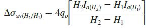
A square foundation, 1.5 m wide, carries a net column load of 500 kN as shown in Figure P8.11. Determine the average stress increase beneath the center of the foundation in the clay layer:a. Using Eq. (8.25),b. Using Eqs. (8.26) and (8.10), andc. Using Eqs. (8.26) and (8.15).Figure P8.11Eq.
A square flexible foundation of width B applies a uniform pressure qo to the underlying ground. Determine the vertical stress increase at a depth of B/2 below the center using:a. Δσ beneath the corner of a uniform rectangular load [Eq. (8.10) and Table 8.5],b. 2:1 method [Eq. (8.15)], andc.
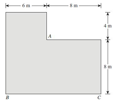
A flexible L-shaped raft shown in Figure P8.9 applies a uniform pressure of 60 kN/m2 to the underlying ground. Find the vertical stress increase at 4 m below A, B, and C.Figure P8.9 - 6 m – - 8 m 4 m A 8m C B
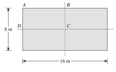
Figure P8.8 shows a flexible rectangular raft that is 8 m × 16 m and applies a uniform pressure of 80 kN/m2 to the underlying ground. Find the vertical stress increase Δσ at 4 m below A, B, C, and D.Figure P8.8 A |B C D 8 m 16 m-
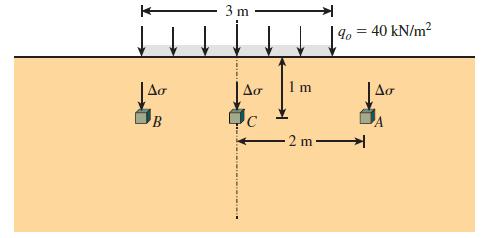
A 3 m wide and infinitely long flexible strip load of 40 kN/m2 is placed on an elastic medium as shown in Figure P8.7. Find the vertical stress increase at points A, B, and C located 1 m below the surface.Figure P8.7. 3 m 9, = 40 kN/m? |Ao Aơ 1 m 2 m
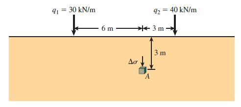
Two line loads q1 and q2 of infinite lengths are acting on top of an elastic medium, as shown in Figure P8.6. Find the vertical stress increase at A.Figure P8.6. 30 kN/m 92 = 40 kN/m %3D 6 m + 3 m 3 m Aơ
For the flexible loaded area in Problem 8.4, plot the vertical stress variation with the radial distance at 0.75 m below the ground level.Problem 8.4A 3 m diameter flexible loaded area is subjected to a uniform pressure of 60 kN/m2.a. Plot the variation of the vertical stress increase beneath the
A 3 m diameter flexible loaded area is subjected to a uniform pressure of 60 kN/m2.a. Plot the variation of the vertical stress increase beneath the center with depth z = 0 to 6 m.b. In the same plot, show the variation beneath the edge of the loaded area.
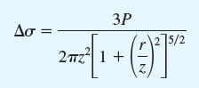
A point load of 1000 kN is applied at the ground level. Plot the variation of the vertical stress increase Δσ with depth at horizontal distance of 1 m, 2 m, and 4 m from the load.
A point load of 500 kN is applied at the ground level. Plot the lateral variation of the vertical stress increase Δσ at depths of 2 m, 3 m, and 4 m below the ground level.
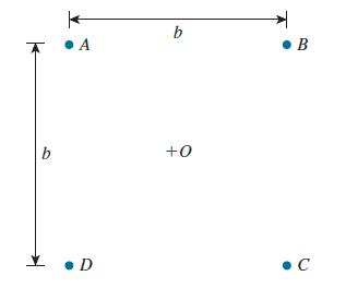
Four point loads with the same magnitude of P are applied as shown in the plan view in Figure P8.1 and are separated by distance b.a. Find the vertical stress increase Δσ at a depth of 0.5b below the points O and A in terms of P and b. Use Boussinesq’s solution given by Eq. (8.1).b. Determine
A foundation measuring 1.2 m × 2.4 m in plan is constructed in a saturated clay. Given: depth of embedment of the foundation = 2 m, unit weight of soil = 18 kN/m3, and undrained cohesion of clay = 74 kN/m2. Estimate the ultimate uplift capacity of the foundation.
A square foundation in a sand deposit measures 1.22 m × 1.22 m in plan. Given: Df = 1.52 m, soil friction angle = 35°, and unit weight of soil = 17.6 kN/m3. Estimate the ultimate uplift capacity of the foundation.
A sandstone bed with RQD = 70% and γ = 26.0 kN/m3 lies beneath 1.5 m of overburden soil. A 2.0 m × 2.0 m square foundation is to be placed on top of the sandstone rock (i.e., at a 1.5 depth below the ground level) to carry a column load. The unit weight of the soil is 18.0 kN/m3. Assuming the
A sandstone rock specimen has quc = 50 MN/m2 and ϕ' = 35°. Find c'.
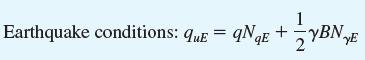
Refer to Problem 7.15. If the design earthquake parameters are V = 0.35 m/s and A = 0.3, determine the seismic settlement of the foundation. Assume FS = 4 for obtaining static allowable bearing capacity.Problem 7.15.The following are the average values of cone penetration resistance in a granular
The following are the average values of cone penetration resistance in a granular soil deposit.Depth (m) …………………… Cone penetration resistance, qc (MN/m2)2 ………………………………………… 1.734 ………………………………………… 3.66
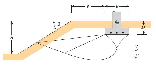
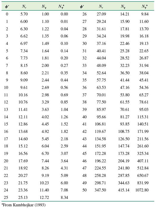
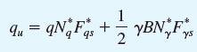
A continuous foundation is to be constructed near a slope made of granular soil (see Figure 7.19). If B = 1.22 m, b = 1.83 m, H = 4.57 m, Df = 1.22 m, β = 30°, ϕ' = 40°, and γ = 17.29 kN/m3, estimate the ultimate bearing capacity of the foundation.Figure 7.19 — В — qu B Dr c'
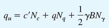
The applied load on a shallow square foundation makes an angle of 208 with the vertical. Given: B = 1.52 m, Df = 0.9 m, γ = 18.08 kN/m3, ϕ' = 258, and c' = 28.75 kN/m2. Use FS = 4 and determine the gross inclined allowable load. Use Eq. (6.28).Eq. (6.28) qu = c'N,FeFcaFeci + qN„FqsFqaFqi +
Redo Problem 6.2 using the general bearing capacity equation [Eq.(6.28)].Eq. (6.28)Problem 6.2A 1.5 m wide square footing is placed at 1 m depth within the ground where c' = 10 kN/m2, ϕ' = 258, and γ = 18 kN/m3. Determine the ultimate bearing capacity of the footing using Terzaghi’s bearing
A 1.5 m wide square footing is placed at 1 m depth within the ground where c' = 10 kN/m2, ϕ' = 258, and γ = 18 kN/m3. Determine the ultimate bearing capacity of the footing using Terzaghi’s bearing capacity equation and the bearing capacity factors from Table 6.1. What is the maximum column
For a cohesive soil with LL = 45 and PL = 25, estimate the difference in the wopt and γd(max) values between standard and modified compaction tests. Use Gurtug and Sridharan (2004) correlations.
A continuous foundation with a width of 1 m is located on a slope made of clay soil. Refer to Figure 7.19 and let Df = 1 m, H = 4 m, b = 2 m, γ = 16.8 kN/m3, c = cu = 68 kN/m2, ϕ = 0, and b = 60°.a. Determine the allowable bearing capacity of the foundation. Let FS = 3.b. Plot a graph of the
Two continuous foundations are constructed alongside each other in a granular soil. Given for the foundation: B = 1.2 m, Df = 1 m, and center-to-center spacing = 2 m. The soil friction angle ϕ' = 35°. Estimate the net allowable bearing capacity of the foundations. Use FS = 4 and a unit weight of
A 2 m wide continuous foundation is to be placed in a saturated clay at 1.5 m depth where cu = 40 kN/m2 and γ = 18.0 kN/m3.a. What is the ultimate bearing capacity of the foundation?b. To increase the ultimate bearing capacity, it is proposed to place dense sand (ϕ' = 42° and γ = 18.5 kN/m3) in
A continuous foundation having a width of 1.5 m is placed at 1.0 m depth within a loose sand deposit where ϕ' = 32° and γ = 17.0 kN/m3. This sand is underlain by a thick dense sand deposit (ϕ' = 40° and γ = 18.0 kN/m3) at 2.5 m depth below the ground level. Determine the ultimate bearing
A 3 m thick clay layer (cu = 60 kN/m2 and γ = 19.0 kN/m3) is underlain by a weaker clay (cu = 30 kN/m2 and γ = 18.0 kN/m3) to a large depth. A 2.0 m wide square foundation is placed at 1.5 m depth below the ground level. Determine the maximum column load that can be allowed on the foundation with
A 2 m wide continuous foundation is placed at 1 m depth within a 1.5 m thick sand layer that is underlain by a weaker clay layer. The soil properties are as follows:Upper sand layer: unit weight = 18.0 kN/m3, ϕ' = 38°Lower clay layer: unit weight = 19.0 kN/m3, undrained shear strength = 25
Redo Problem 7.6 using Vesic’s (1975) solution [Eq. (7.12)].Eq. (7.12)Problem 7.6A 2.0 m wide continuous foundation is placed at 1.5 m depth in a saturated clay where cu = 40 kN/m2 and γ = 18.5 kN/m3. At 2.0 m below the ground level, this clay layer is underlain by a stiffer clay where cu = 60
A 2.0 m wide continuous foundation is placed at 1.5 m depth in a saturated clay where cu = 40 kN/m2 and γ = 18.5 kN/m3. At 2.0 m below the ground level, this clay layer is underlain by a stiffer clay where cu = 60 kN/m2 and γ = 19.0 kN/m3. What would be the maximum wall load allowed with FS = 3?
A 2.0 m wide square foundation is placed at 0.5 m depth in a saturated clay where cu = 40 kN/m2 and γ = 19.0 kN/m3. There is a very stiff stratum present at 1.0 m below the foundation. Determine the ultimate bearing capacity using Buisman’s (1940) equation.
In Problem 7.3, if no bedrock was present for at least 4 m below the foundation, determine the ultimate bearing capacity.Problem 7.3A 1.5 m × 2.0 m rectangular foundation is placed at 1.0 m depth in sand where ϕ' = 40° and γ = 18.5 kN/m3. Bedrock is present at 1.0 m below the foundation. Using
A 1.5 m × 2.0 m rectangular foundation is placed at 1.0 m depth in sand where ϕ' = 40° and γ = 18.5 kN/m3. Bedrock is present at 1.0 m below the foundation. Using Eq. (7.3), determine the ultimate bearing capacity of the foundation.Eq. (7.3) Gu = qNF YBN F 9* qs y* ys 1/- +
In Problem 7.1, if there was no bedrock present for at least 4 m below the foundation, what would the ultimate bearing capacity be?Problem 7.1A 2.5 m wide rough continuous foundation is placed in the ground at 1 m depth. There is bedrock present at 1 m depth below the bottom of the foundation. The
A 2.5 m wide rough continuous foundation is placed in the ground at 1 m depth. There is bedrock present at 1 m depth below the bottom of the foundation. The soil properties are c' = 10.0 kN/m2, ϕ' = 25°, and γ = 18.0 kN/m3. Determine the ultimate bearing capacity of the foundation.
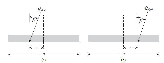
Consider a continuous foundation of width B = 1.4 m on a sand deposit with c' = 0, ϕ' = 38°, and γ = 17.5 kN/m3. The foundation is subjected to an eccentrically inclined load (see Figure 6.33). Given: load eccentricity e = 0.15 m, Df = 1 m, and load inclination γ = 18°. Estimate the failure
The shallow foundation shown in Figure 6.25 measures 1.5 m × 2.25 m and is subjected to a centric load and a moment. If eB = 0.12 m, eL = 0.36 m, and the depth of the foundation is 0.8 m, determine the allowable load the foundation can carry. Use a factor of safety of 4. For the soil, we are told
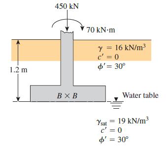
A square foundation is shown in Figure P6.19. Use FS = 6, and determine the size of the foundation. Use Prakash and Saran's method [Eq. (6.59)].Figure P6.19. 450 kN 70 kN-m y = 16 kN/m3 c' = 0 o'= 30° %3D %3D 1.2 m BX B Water table Ysat = 19 kN/m c' = 0 %3D o' = 30° %3D
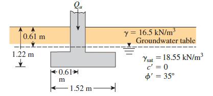
An eccentrically loaded continuous foundation is shown in Figure P6.18. Determine the ultimate load Qu per unit length that the foundation can carry. Use the reduction factor method [Eq. (6.67)].Figure P6.18. Qu 0.61 m y = 16.5 kN/m Groundwater table 1.22 m Ysat = 18.55 kN/m3 c' = 0 o' = 35°
A 2.0 m × 2.0 m square pad footing will be placed in a normally consolidated clay soil to carry a column load Q. The depth of the footing is 1.0 m. The soil parameters are: c' = 0, ϕ' = 26°, γ = 19 kN/m3, and cu = 60 kN/m2. Determine the maximum possible value for Q, considering short-term and
A tall cylindrical silo carrying flour is to be supported by a 1.5 m wide ring beam that can be designed as a continuous foundation. The inner and outer diameters of the ring are 10 m and 13 m, respectively. The soil at the site is entirely sand (ϕ' = 35°, γ = 19 kN/m3) and the ring beam is
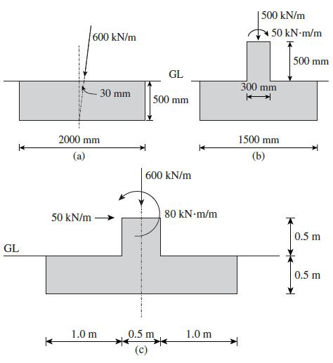
Three continuous foundations are shown in Figure P6.15. For each of them, what values would you use for their eccentricity and inclination in the bearing capacity calculations?Figure P6.15. |500 kN/m 600 kN/m 50 kN-m/m 500 mm GL 300 mm 30 mm 500 mm 2000 mm 1500 mm (a) (b) 600 kN/m 80 kN-m/m 50 kN/m
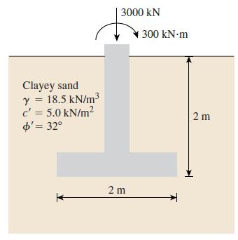
A 2 m × 3 m spread footing placed at a depth of 2 m carries a vertical load of 3000 kN and a moment of 300 kN ∙ m, as shown in Figure P6.14. Determine the factor of safety using Meyerhof’s effective area method.Figure P6.14. 3000 kN 300 kN-m Clayey sand y = 18.5 kN/m3 c' = 5.0 kN/m? d'=
For an eccentrically loaded continuous foundation on sand, given B = 1.8 m, Df = 0.9 m, e/B = 0.12 (one-way eccentricity), γ = 16 kN/m3, and ϕ' = 35°. Using the reduction factor method [Eq. (6.64)], estimate the ultimate load per unit length of the foundation.
Repeat Problem 6.11 using Prakash and Saran’s method.Problem 6.11An eccentrically loaded foundation is shown in Figure P6.11. Use FS of 4 and determine the maximum allowable load that the foundation can carry. Use Meyerhof’s effective area method.Figure P6.11. (Eccentricity in one direction
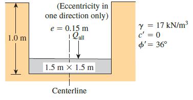
An eccentrically loaded foundation is shown in Figure P6.11. Use FS of 4 and determine the maximum allowable load that the foundation can carry. Use Meyerhof’s effective area method.Figure P6.11. (Eccentricity in one direction only) Y = 17 kN/m c' = 0 o'= 36° e = 0.15 m %3D 1.0 m 1.5 m x 1.5 m
For the design of a shallow foundation, given the following:Soil: ϕ' = 20°c' = 72 kN/m2Unit weight, γ = 17 kN/m3Modulus of elasticity, Es = 1400 kN/m2Poisson’s ratio, µs = 0.35Foundation: L = 2 mB = 1 mDf = 1 mCalculate the ultimate bearing capacity. Use Eq. (6.42).Eq. (6.42) 4u = c'NFFeF ce
Showing 100 - 200
of 271
1
2
3
Step by Step Answers