

Question: Design a shifter circuit, similar to the one in Figure 4.50, which can shift a four-bit input vector, W = w 3 w 2 w
Design a shifter circuit, similar to the one in Figure 4.50, which can shift a four-bit input vector, W = w3w2w1w0, one bit-position to the right when the control signal Right is equal to 1, and one bit-position to the left when the control signal Left is equal to 1. When Right = Left = 0, the output of the circuit should be the same as the input vector. Assume that he condition Right = Left = 1 will never occur.
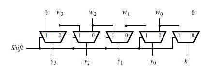
Shift 0 W3 Y3 0. W2 1/2 0 W1 Y 0 Wo Yo 0, k 0 0
Step by Step Solution
3.37 Rating (175 Votes )
There are 3 Steps involved in it
Solution The design is as follow i The first stage of the shift register must be able to perform a s... View full answer

Get step-by-step solutions from verified subject matter experts