

Question: Compile and simulate the 4-bit adder in Figure 3-50. Apply combinations that check out the rightmost full adder for all eight input combinations; this also
Compile and simulate the 4-bit adder in Figure 3-50. Apply combinations that check out the rightmost full adder for all eight input combinations; this also serves as a check for the other full adders. Also, apply combinations that check the carry chain connections between all full adders by demonstrating that a 0 and a 1 can be propagated from C0 to C4.
Figure 3-50
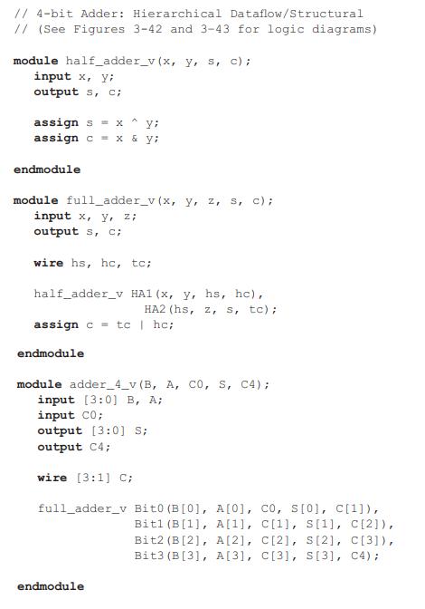
// 4-bit Adder: Hierarchical Dataflow/Structural // (See Figures 3-42 and 3-43 for logic diagrams) module half_adder_v (x, y, s, c); input x, y; output s, C; assign sx y; assign c = x & y; endmodule module full_adder_v (x, y, z, s, c); input x, y, z; output s, c; wire hs, hc, tc; half_adder_v HA1 (x, y, hs, hc), HA2 (hs, z, s, tc); assign c = tc | hc; endmodule module adder_4_v (B, A, CO, S, C4); input [3:0) B, A; input C0; output [3:0] S; output C4; wire [3:1] C; full_adder v Bit0 (B[0], A [0], co, s[0], c[1]), Bitl (B[1], A[1], C [1], S[1], C[2]), Bit2 (B[2], A [2], C[2], S[2], C[3]), Bit3 (B [3], A [3], C[3], S[3], C4); endmodule
Step by Step Solution
3.42 Rating (161 Votes )
There are 3 Steps involved in it
The image shows a Verilog code representing a 4bit adder composed of modules for a half adder full adder and a 4bit adder that uses the full adders Th... View full answer

Get step-by-step solutions from verified subject matter experts