

Question: Digital circuits require actions to take place at precise times, so they are controlled by a clock that generates a steady sequence of rectangular voltage
Digital circuits require actions to take place at precise times, so they are controlled by a clock that generates a steady sequence of rectangular voltage pulses. One of the most widely used integrated circuits for creating clock pulses is called a 555 timer. FIGURE P28.77 shows how the timer??s output pulses, oscillating between 0 V and 5 V, are controlled with two resistors and a capacitor. The circuit manufacturer tells users that TH, the time the clock output spends in the high (5 V) state, is TH= (R1+ R2) C × ln 2. Similarly, the time spent in the low (0 V) state is TL= R2C × ln 2. You need to design a clock that will oscillate at 10 MHz and will spend 75% of each cycle in the high state. You will be using a 500 pF capacitor. What values do you need to specify for R1and R2?
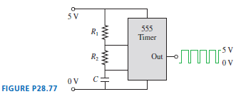
5 V 555 Timer R -5 V Out t OV FIGURE P28.77
Step by Step Solution
3.56 Rating (170 Votes )
There are 3 Steps involved in it
Model T T H T L Visualize We are given Solve Given T 100 ns we surmise that ... View full answer

Get step-by-step solutions from verified subject matter experts
Document Format (2 attachments)
1442_6054778bbd2a8_694423.pdf
180 KBs PDF File
1442_6054778bbd2a8_694423.docx
120 KBs Word File