

Question: (0) Write the final equation for each output of each circuit and draw the truth table for the same. (ii) Implement the circuits on your
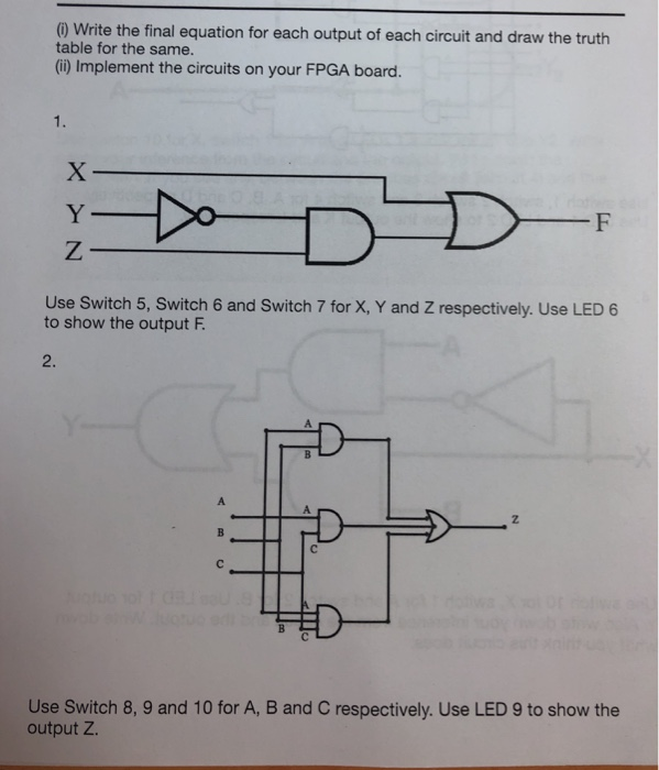
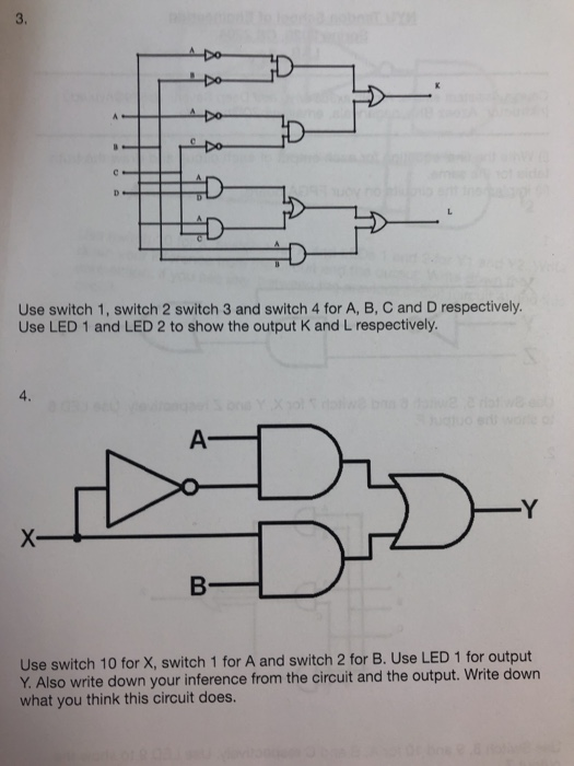
(0) Write the final equation for each output of each circuit and draw the truth table for the same. (ii) Implement the circuits on your FPGA board. F Use Switch 5, Switch 6 and Switch 7 for X, Y and Z respectively. Use LED 6 to show the output F. Use Switch 8, 9 and 10 for A, B and C respectively. Use LED 9 to show the output Z. Use switch 1, switch 2 switch 3 and switch 4 for A, B, C and D respectively. Use LED 1 and LED 2 to show the output K and L respectively. Use switch 10 for X, switch 1 for A and switch 2 for B. Use LED 1 for output Y. Also write down your inference from the circuit and the output. Write down what you think this circuit does. (0) Write the final equation for each output of each circuit and draw the truth table for the same. (ii) Implement the circuits on your FPGA board. F Use Switch 5, Switch 6 and Switch 7 for X, Y and Z respectively. Use LED 6 to show the output F. Use Switch 8, 9 and 10 for A, B and C respectively. Use LED 9 to show the output Z. Use switch 1, switch 2 switch 3 and switch 4 for A, B, C and D respectively. Use LED 1 and LED 2 to show the output K and L respectively. Use switch 10 for X, switch 1 for A and switch 2 for B. Use LED 1 for output Y. Also write down your inference from the circuit and the output. Write down what you think this circuit does
Step by Step Solution
There are 3 Steps involved in it

Get step-by-step solutions from verified subject matter experts