

Question: 2. Design a MOSFET-C fully-balanced filter based on the continuous-time filter prototype as shown in Fig. 2. Determine the unknown component values in the filter
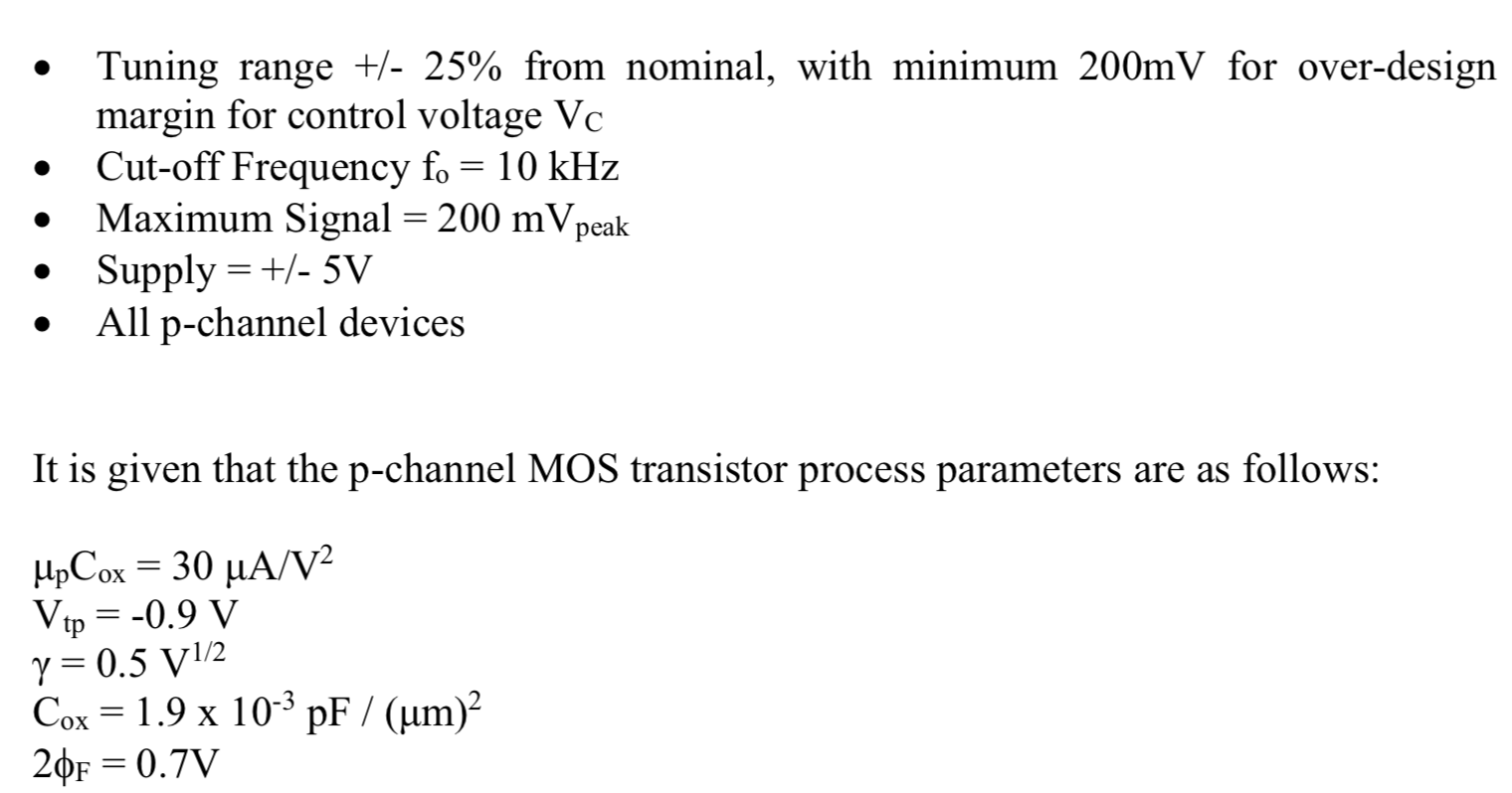
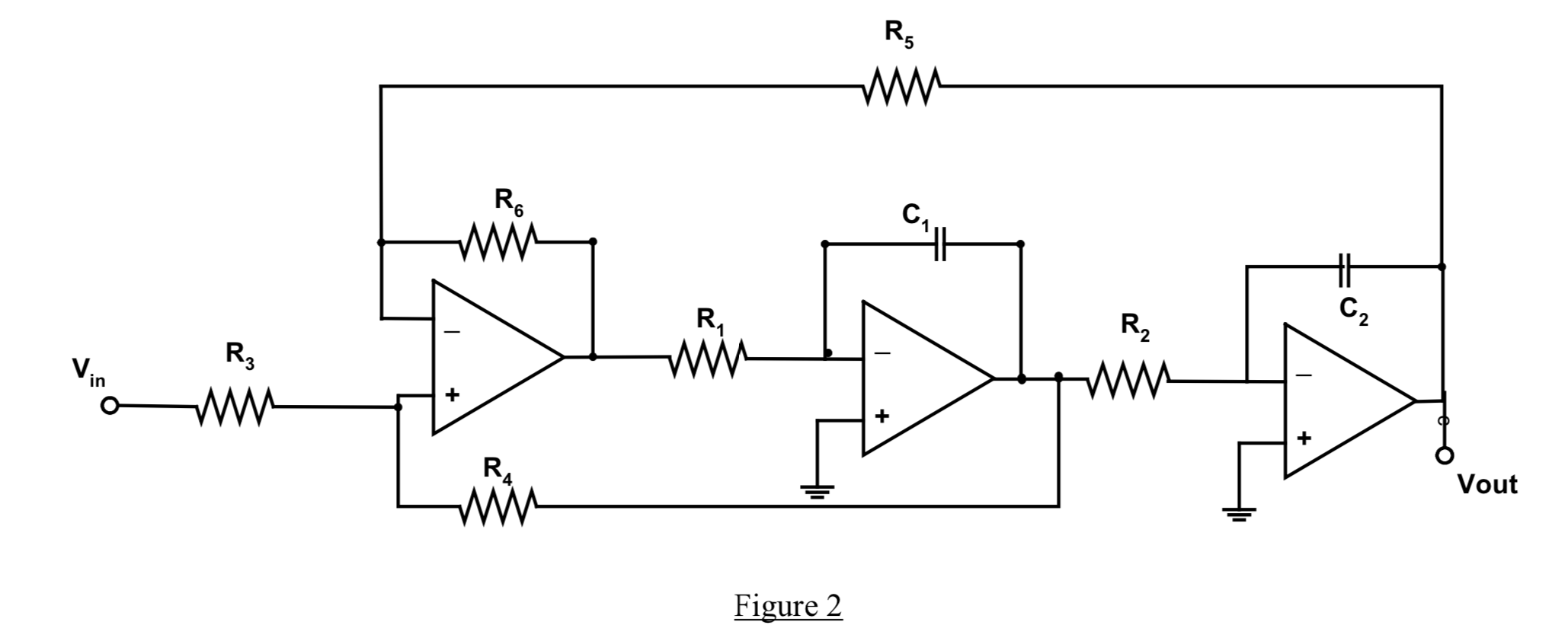
2. Design a MOSFET-C fully-balanced filter based on the continuous-time filter prototype as shown in Fig. 2. Determine the unknown component values in the filter prototype at nominal cut-off frequency. In the MOSFET-C filter design, find the tuning range of the control signal on the MOSFET-C filter and all the channel lengths for MOSFET resistors. State the assumptions. The specifications of the MOSFET-C filter are given as follows: Low-pass Butterworth response H(s) = Ho 002/[S+ (@0/Q)S + @0], where the symbols have their usual meanings. Q=0.707, DC gain = 0 dB C1=C2 = 20 pF Channel width of MOSFET devices = 5um Tuning range +/- 25% from nominal, with minimum 200mV for over-design margin for control voltage Vo Cut-off Frequency fo = 10 kHz Maximum Signal = 200 mV peak Supply = +/- 5V All p-channel devices It is given that the p-channel MOS transistor process parameters are as follows: UpCox = 30 uA/V2 Vtp = -0.9 V y = 0.5 V1/2 Cox = 1.9 x 10- pF / (um)? 20F = 0.7V R, RO W- t R, C2 R2 Vin Rz + + RA Vout Figure 2 2. Design a MOSFET-C fully-balanced filter based on the continuous-time filter prototype as shown in Fig. 2. Determine the unknown component values in the filter prototype at nominal cut-off frequency. In the MOSFET-C filter design, find the tuning range of the control signal on the MOSFET-C filter and all the channel lengths for MOSFET resistors. State the assumptions. The specifications of the MOSFET-C filter are given as follows: Low-pass Butterworth response H(s) = Ho 002/[S+ (@0/Q)S + @0], where the symbols have their usual meanings. Q=0.707, DC gain = 0 dB C1=C2 = 20 pF Channel width of MOSFET devices = 5um Tuning range +/- 25% from nominal, with minimum 200mV for over-design margin for control voltage Vo Cut-off Frequency fo = 10 kHz Maximum Signal = 200 mV peak Supply = +/- 5V All p-channel devices It is given that the p-channel MOS transistor process parameters are as follows: UpCox = 30 uA/V2 Vtp = -0.9 V y = 0.5 V1/2 Cox = 1.9 x 10- pF / (um)? 20F = 0.7V R, RO W- t R, C2 R2 Vin Rz + + RA Vout Figure 2
Step by Step Solution
There are 3 Steps involved in it

Get step-by-step solutions from verified subject matter experts