

Question: 3. Clock Divider (A) Design a clock divider that converts a 20MHz input clock to a lM clock output using an Hitbinary do co ter
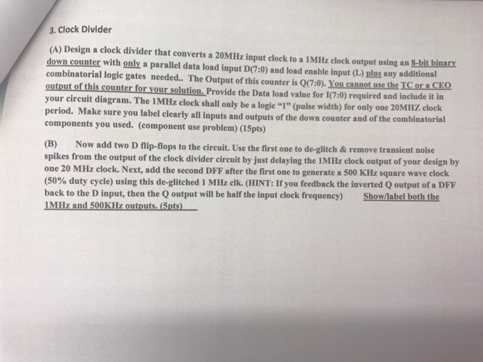
3. Clock Divider (A) Design a clock divider that converts a 20MHz input clock to a lM clock output using an Hitbinary do co ter with only a parallel data load input D(7:0) and load enable input (L) plus any additional combinatorial logic gates needed.. The Output of this counter is Q(7:0). You cannot use the TC or a CEO output of this counter for your solution. Provide the Data load value for 1(7:0) required and include it in your circuit diagram. The 1MHz elock shall only be a logie "1" (pulse width) for only one 20MHZ clock period. Make sure you label clearly all inputs and outputs of the down counter and of the combinatorial components you used. (component use problem) (15pts) Now add two D flip-flops to the circuit. Use the first one to de-glitch & remove transient noise spikes from the output of the cloek divider circuit by just delaying the IMHz clock output of your design by one 20 MHz clock. Next, add the second DFF after the first one to generate a 500 KHz square wave clock (50% duty cycle) using this de-glitched 1 MHz clk. (HINT: If you feedback the inverted Q output of a DFF back to the D input, then the Q output will be half the input clock frequency) Show/label both the
Step by Step Solution
There are 3 Steps involved in it

Get step-by-step solutions from verified subject matter experts