

Question: a. Write a behavioral Verilog description for the state diagram shown in figure1. b. Write a Structural Verilog description for the circuit shown in
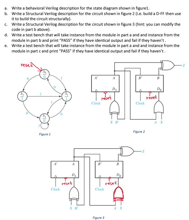
a. Write a behavioral Verilog description for the state diagram shown in figure1. b. Write a Structural Verilog description for the circuit shown in figure 2 (i.e. build a D-FF then use it to build the circuit structurally). c. Write a Structural Verilog description for the circuit shown in figure 3 (hint: you can modify the code in part b above). d. Write a test bench that will take instance from the module in part a and and instance from the module in part b and print "PASS" if they have identical output and fail if they haven't. Write a test bench that will take instance from the module in part a and and instance from the module in part c and print "PASS" if they have identical output and fail if they haven't. e. reset 0 Figure 1 A' Clock 0 A DA reset X B' A' Clock reset B' Clock Figure 3 A DA X B' B DB reset D A X B' Clock Figure 2 rset B DB AX
Step by Step Solution
3.37 Rating (144 Votes )
There are 3 Steps involved in it
Based on your description I can analyze the prompt and provide a response to the mathematical problem about a linear programming LP graphical solution ... View full answer

Get step-by-step solutions from verified subject matter experts