

Question: Create the Solid Model represented by the two-view drawing shown in Figure below in SolidWorks. Then create the two-view drawing and add the geometric
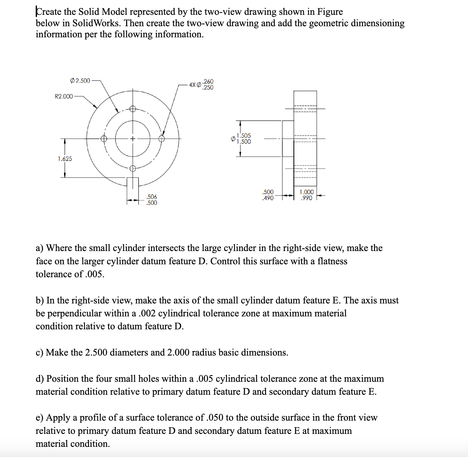
Create the Solid Model represented by the two-view drawing shown in Figure below in SolidWorks. Then create the two-view drawing and add the geometric dimensioning information per the following information. R2.000 1.625 2.500 .506 .500 .260 250 1.505 1.500 .500 .490 1.000 .990 a) Where the small cylinder intersects the large cylinder in the right-side view, make the face on the larger cylinder datum feature D. Control this surface with a flatness tolerance of .005. b) In the right-side view, make the axis of the small cylinder datum feature E. The axis must be perpendicular within a .002 cylindrical tolerance zone at maximum material condition relative to datum feature D. c) Make the 2.500 diameters and 2.000 radius basic dimensions. d) Position the four small holes within a .005 cylindrical tolerance zone at the maximum material condition relative to primary datum feature D and secondary datum feature E. e) Apply a profile of a surface tolerance of .050 to the outside surface in the front view relative to primary datum feature D and secondary datum feature E at maximum material condition.
Step by Step Solution
There are 3 Steps involved in it

Get step-by-step solutions from verified subject matter experts