

Question: CS101 Lab #3: Logic Circuits For this lab, you'll use a web-based logic simulator to create a series of logic circuits. The Simulator is available
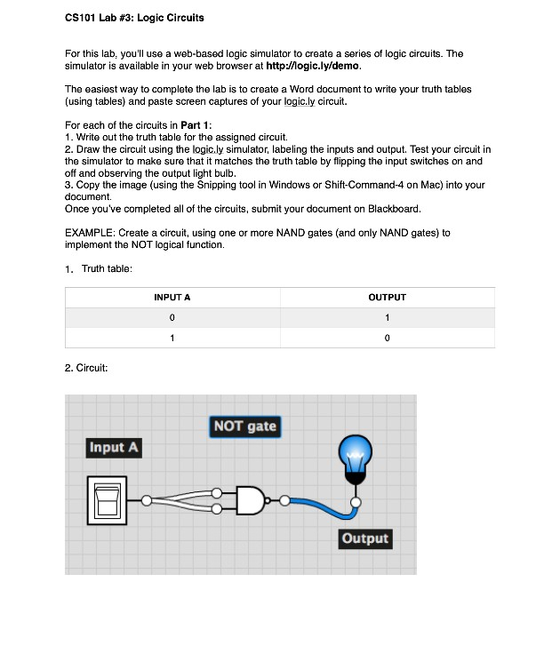

CS101 Lab #3: Logic Circuits For this lab, you'll use a web-based logic simulator to create a series of logic circuits. The Simulator is available in your web browser at http://ogic.ly/demo. The easiest way to complete the lab is to create a Word document to write your truth tables (using tables) and paste screen captures of your logic.ly circuit. For each of the circuits in Part 1: 1. Write out the truth table for the assigned circuit. 2. Draw the circuit using the logic.ly simulator, labeling the inputs and output. Test your circuit in the simulator to make sure that it matches the truth table by flipping the input switches on and off and observing the output light bulb. 3. Copy the image (using the Snipping tool in Windows or Shift-Command-4 on Mac) into your document. Once you've completed all of the circuits, submit your document on Blackboard. EXAMPLE: Create a circuit, using one or more NAND gates (and only NAND gates) to implement the NOT logical function. 1. Truth table: INPUT A OUTPUT 2. Circuit: NOT gate Input A Output Circult #3: An AND gate Using just two NAND gates, create an AND function with two inputs and one output. Write the truth table first for the circuit. Circuit #4: An XOR gate (not graded, just for fun) Using just four NAND gates, create an EXCLUSIVE OR function with two inputs and one output. Part 1 Circuit #1: An OR gate Using just three NAND gates, create an OR function with two inputs and one output. Write the truth table first for the circuit. Hint: You might need to tie some inputs together, similar to the input in the example circuit. Circuit #2: A NOR gate Using just four NAND gates, create a NOR (not OR) function with two inputs and one output. Write the truth table first for the circuit. Hint: You might need to tie some inputs together, similar to the input in the example circuit
Step by Step Solution
There are 3 Steps involved in it

Get step-by-step solutions from verified subject matter experts