

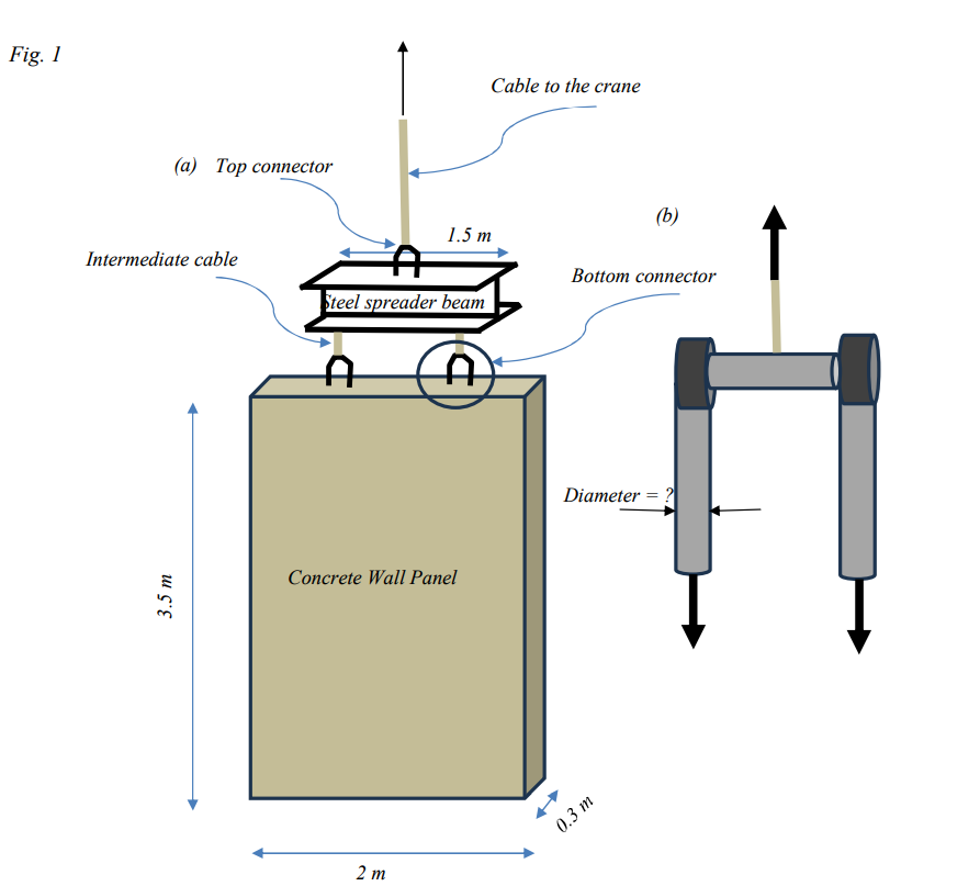
Question: Fig. 1 shows a set - up for lifting concrete wall panels. Round steel bars embedded in the concrete ( see Fig. 1 b )
Fig. shows a setup for lifting concrete wall panels. Round steel bars embedded in the concrete see Fig. b will be connected by cables to the bottom of the steel spreader beam. A connector at the top of the steel beam will have a design similar to that seen in Fig. b
There will be a third cable connecting to the crane.
The steel cable has an ultimate strength of MPa.
The round steel bars for the connectors have an ultimate strength of MPa. Everything should be designed for a factor of safety of
The dimension of the concrete panel are shown. The steel spreader beam has a crosssectional area of mm
Calculations should account for the weight of the concrete panel and steel beam, but you can assume the weight of everything else is negligible.
Use the following densities to calculate weights:
Concrete: kgm
Steel: kgm
a Determine the required diameter for the bottom connectors.
b Determine the required diameter for the two intermediate cables.
c Determine the required diameter for the top connector.
d Determine the required diameter for the cable connecting to the crane.
Your solution must include clear freebody diagrams at each of the critical locations in the system
Step by Step Solution
There are 3 Steps involved in it
1 Expert Approved Answer
Step: 1 Unlock

Question Has Been Solved by an Expert!
Get step-by-step solutions from verified subject matter experts
Step: 2 Unlock
Step: 3 Unlock