

Question: Figure 1: MIPS single-cycle diagram for part E MI ul Add Add. ALU result 4 Shift left 2 RegDst Branch MemRead MemtoRe Instruction [31-26] Control
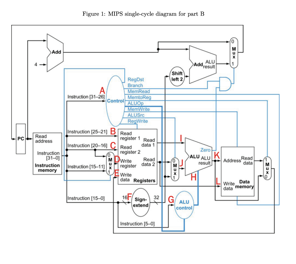
Figure 1: MIPS single-cycle diagram for part E MI ul Add Add. ALU result 4 Shift left 2 RegDst Branch MemRead MemtoRe Instruction [31-26] Control ALUO MemWrite ALUSrc RegWrite Instruction |25-21] B Read Read address register 1 Read Instruction [20-16] CRead data 1 Read PC Zero ALU ALU result Instruction register 2 31-0 0 MI Read Address data Instruction Instruction [15-11register data memory Write data Registers Write Data data memor Instruction [15-0] 16 Sign ALU control extend Instruction [5-0] Figure 1: MIPS single-cycle diagram for part E MI ul Add Add. ALU result 4 Shift left 2 RegDst Branch MemRead MemtoRe Instruction [31-26] Control ALUO MemWrite ALUSrc RegWrite Instruction |25-21] B Read Read address register 1 Read Instruction [20-16] CRead data 1 Read PC Zero ALU ALU result Instruction register 2 31-0 0 MI Read Address data Instruction Instruction [15-11register data memory Write data Registers Write Data data memor Instruction [15-0] 16 Sign ALU control extend Instruction [5-0]
Step by Step Solution
There are 3 Steps involved in it

Get step-by-step solutions from verified subject matter experts