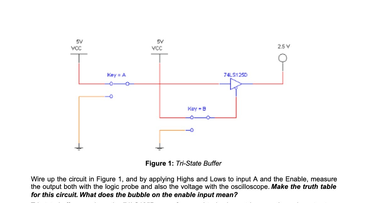
Question: Figure 1: T-State Buffer Wire up the circuit in Figure 1, and by applying Highs and Lows to input A and the Enable, measure the

Figure 1: T-State Buffer Wire up the circuit in
Figure 1: T-State Buffer Wire up the circuit in Figure 1, and by applying Highs and Lows to input A and the Enable, measure the output both with the logic probe and also the voltage with the oscilloscope. Make the truth table for this circuit. What does the bubble on the enabte input mean

Step by Step Solution

There are 3 Steps involved in it

1 Expert Approved Answer
Step: 1 Unlock blur-text-image
Question Has Been Solved by an Expert!

Get step-by-step solutions from verified subject matter experts

Step: 2 Unlock
Step: 3 Unlock

Students Have Also Explored These Related Mathematics Questions!