

Question: I need help creating the Verilog code for my pre lab. Your task is to implement (on the Basys3 board) the module M described below:
I need help creating the Verilog code for my pre lab.
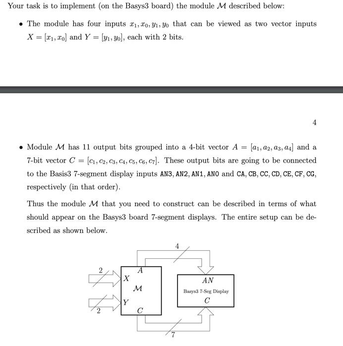
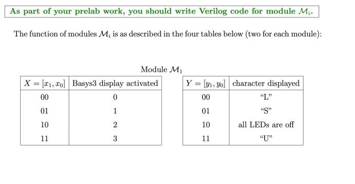
Your task is to implement (on the Basys3 board) the module M described below: The module has four inputs 11,20, 41, yo that can be viewed as two vector inputs X = [X1, Xo] and Y = (y1, yo), each with 2 bits. 4 Module M has 11 output bits grouped into a 4-bit vector A = (01, 02, 03, 04] and a 7-bit vector C = (C1,C2, C3, C4, C5, C6, 07). These output bits are going to be connected to the Basis3 7-segment display inputs AN3, AN2, AN1, ANO and CA, CB, CC, CD, CE, CF, CG, respectively in that order). Thus the module M that you need to construct can be described in terms of what should appear on the Basys3 board 7-segment displays. The entire set up can scribed as shown below. X M AN Basys3 7-Seg Display Th Y As part of your prelab work, you should write Verilog code for module Mi. The function of modules Mi is as described in the four tables below (two for each module): Module M X = (01, xo] Basys3 display activated 00 0 01 1 Y = (y1, yol character displayed 00 01 "S" 10 all LEDs are off 11 10 2 11 3
Step by Step Solution
There are 3 Steps involved in it

Get step-by-step solutions from verified subject matter experts