

Question: Implement the state diagram shown below with three D flip-flops and logic gates using the state encoding given on its right. Its initial state should
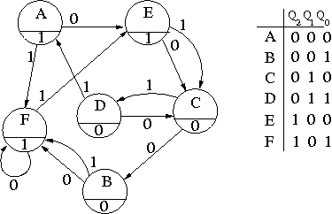
Implement the state diagram shown below with three D flip-flops and logic gates using the state encoding given on its right. Its initial state should A. Use x the label of the input.
Give the state transition and output table.
Obtain minimal SOP expressions for your next state and output logic using K-maps.
Draw the completed logic diagram for your sequential circuit.
Count the number of gates and literals in the logic
P 1 0 1 0 1 (3001100 3000011 ABCDEF 0 0. 1 DO 1 0
Step by Step Solution
There are 3 Steps involved in it
1 Expert Approved Answer
Step: 1 Unlock

Question Has Been Solved by an Expert!
Get step-by-step solutions from verified subject matter experts
Step: 2 Unlock
Step: 3 Unlock