

Question: MATLAB We are trying to write a FEM application that plots nodes and Eleemnts that we assign but 1) How can i show my node's
MATLAB
We are trying to write a FEM application that plots nodes and Eleemnts that we assign but
1) How can i show my node's boundary conditions with a triangle
2) How can i show my force BC by a arrow which positions itself according to the nodes and elements around it.
This program basically takes nodes and then elements as matrix and doing some calculations then gives another matrix after this you are addin boundary conditions to proceed. At this position i want to add a path to Apply button in boundary conditions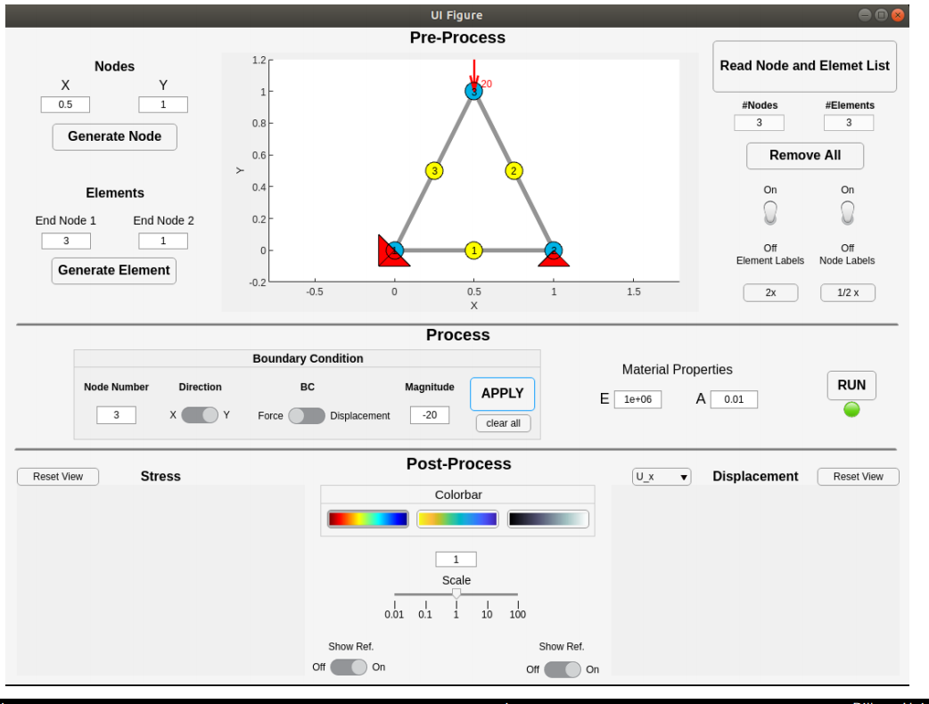
UI Figure Pre-Process Nodes 1.2 Read Node and Elemet List Y 1 1 0.5 #Nodes 3 #Elements 3 0.8 Generate Node 0.6 Remove All 0.4 Elements On On End Node 2 0.2 End Node 1 3 1 Off Off Element Labels Node Labels Generate Element -0.2 -0.5 0 1 1.5 0.5 X 2x 1/2 x Process Boundary Condition Material Properties Node Number Direction BC Magnitude APPLY RUN E le+06 A 0.01 3 Y Force Displacement -20 clear all Post-Process Reset View Stress |ux Displacement Reset View Colorbar 1 Scale od of i 16 160 Show Ref. Show Ref. Off On Off On UI Figure Pre-Process Nodes 1.2 Read Node and Elemet List Y 1 1 0.5 #Nodes 3 #Elements 3 0.8 Generate Node 0.6 Remove All 0.4 Elements On On End Node 2 0.2 End Node 1 3 1 Off Off Element Labels Node Labels Generate Element -0.2 -0.5 0 1 1.5 0.5 X 2x 1/2 x Process Boundary Condition Material Properties Node Number Direction BC Magnitude APPLY RUN E le+06 A 0.01 3 Y Force Displacement -20 clear all Post-Process Reset View Stress |ux Displacement Reset View Colorbar 1 Scale od of i 16 160 Show Ref. Show Ref. Off On Off On
Step by Step Solution
There are 3 Steps involved in it

Get step-by-step solutions from verified subject matter experts