

Question: N. Write a Verilog code that describes the following figure. The figure represents the register file (32x32) with its inputs and outputs as shown. Assume
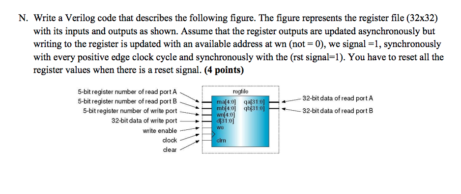
N. Write a Verilog code that describes the following figure. The figure represents the register file (32x32) with its inputs and outputs as shown. Assume that the register outputs are updated asynchronously but writing to the register is updated with an available address at wn (not -0), we signal -1, synchronously with every positive edge clock cycle and synchronously with the (rst signal-1). You have to reset all the register values when there is a reset si gnal. (4 points) 5-bit register number of read port A regtile 32-bit data of read portA 5-bit register number ofread portB* 5-bit register number of write port b4o 132-bit data of read portB 32-bit data of write port> d31:0] we write enable clock clear clrn
Step by Step Solution
There are 3 Steps involved in it

Get step-by-step solutions from verified subject matter experts