

Question: PART 1: NMOS IN SATURATION MODE Consider the circuit shown in Figure L5.3.1: RD R: R R$ FIGURE L5.3.1: NMOS-based circuit for saturation and triode-mode
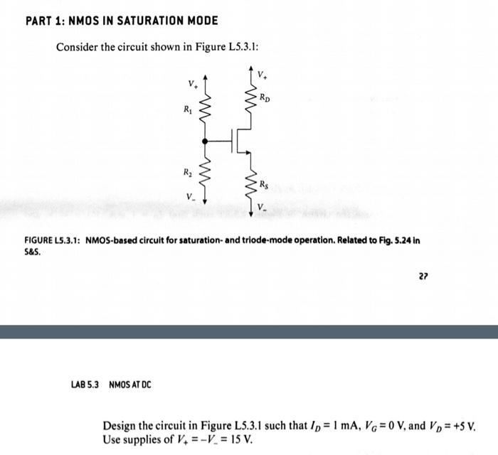
PART 1: NMOS IN SATURATION MODE Consider the circuit shown in Figure L5.3.1: RD R: R R$ FIGURE L5.3.1: NMOS-based circuit for saturation and triode-mode operation. Related to Fig. 5.24 in S&S. 27 LAB 5.3 NMOS AT DC Design the circuit in Figure L5.3.1 such that ID = 1 mA, Vo = 0 V, and V) = +5 V. Use supplies of V. =-V = 15 V. Simulation Simulate your circuit using the values of Rs, Rd, R1, and Ry based on your preceding calculations. Report the values of V, V, V, and I). How closely do they match your calculations? (Remember: The simulator has its own, more complex model of the real transistor, so there should be some small variations.)
Step by Step Solution
There are 3 Steps involved in it
1 Expert Approved Answer
Step: 1 Unlock

Question Has Been Solved by an Expert!
Get step-by-step solutions from verified subject matter experts
Step: 2 Unlock
Step: 3 Unlock