

Question: Perform the following steps within Packet Tracer using the Cisco 2960 for the switches, to complete this practice lab. 1. Cable the network based
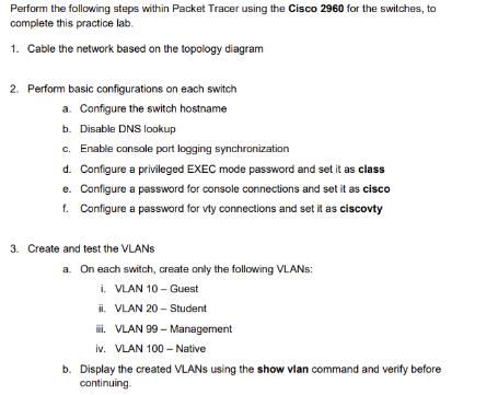
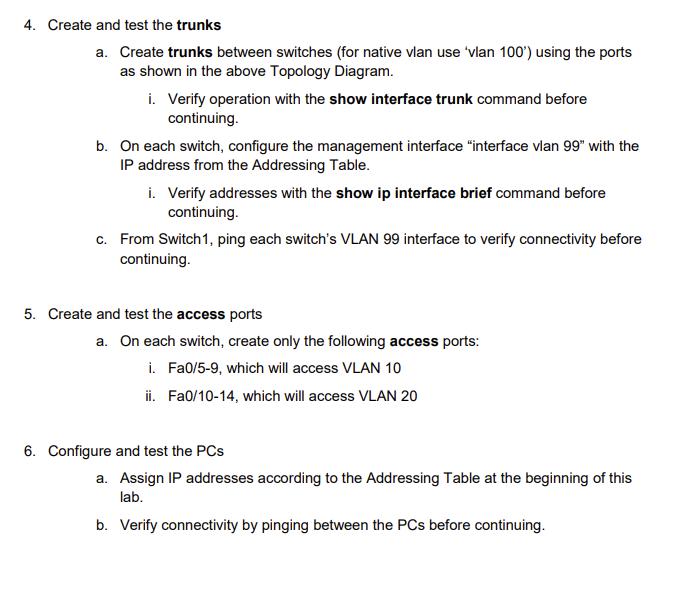
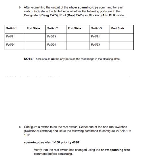
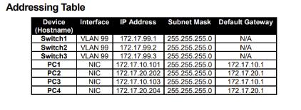
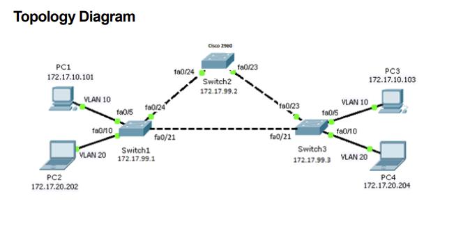
Perform the following steps within Packet Tracer using the Cisco 2960 for the switches, to complete this practice lab. 1. Cable the network based on the topology diagram 2. Perform basic configurations on each switch a. Configure the switch hostname b. Disable DNS lookup c. Enable console port logging synchronization d. Configure a privileged EXEC mode password and set it as class e. Configure a password for console connections and set it as cisco 1. Configure a password for vty connections and set it as ciscovty 3. Create and test the VLANS a. On each switch, create only the following VLANS: i. VLAN 10- Guest ii. VLAN 20-Student iii. VLAN 99-Management iv. VLAN 100 -Native b. Display the created VLANs using the show vlan command and verify before continuing. 4. Create and test the trunks a. Create trunks between switches (for native vlan use 'vlan 100') using the ports as shown in the above Topology Diagram. i. Verify operation with the show interface trunk command before continuing. b. On each switch, configure the management interface "interface vlan 99" with the IP address from the Addressing Table. i. Verify addresses with the show ip interface brief command before continuing. c. From Switch 1, ping each switch's VLAN 99 interface to verify connectivity before continuing. 5. Create and test the access ports a. On each switch, create only the following access ports: i. Fa0/5-9, which will access VLAN 10 ii. Fa0/10-14, which will access VLAN 20 6. Configure and test the PCs a. Assign IP addresses according to the Addressing Table at the beginning of this lab. b. Verify connectivity by pinging between the PCs before continuing. Switch1 Fa0/21 Fa0/24 b. After examining the output of the show spanning-tree command for each switch, indicate in the table below whether the following ports are in the Designated (Desg FWD), Root (Root FWD), or Blocking (Altn BLK) state. Port State Switch2 Fa0/23 Fa0/24 Port State Switch3 Fa0/21 spanning-tree vlan 1-100 priority 4096 Fa0/23 Port State NOTE: There should not be any ports on the root bridge in the blocking state. c. Configure a switch to be the root switch. Select one of the non-root switches (Switch2 or Switch3) and issue the following command to configure VLANs 1 to 100: Verify that the root switch has changed using the show spanning-tree command before continuing. Addressing Table Device Interface IP Address (Hostname) Switch1 Switch2 Switch3 PC1 PC2 PC3 PC4 VLAN 99 VLAN 99 VLAN 99 Subnet Mask Default Gateway 172.17.99.1 255.255.255.0 N/A 172.17.99.2 255.255.255.0 N/A 172.17.99.3 255.255.255.0 N/A 172.17.10.101 255.255.255.0 172.17.10.1 NIC NIC NIC NIC 172.17.20.202 255.255.255.0 172.17.20.1 172.17.10.103 255.255.255.0 172.17.10.1 172.17.20.204 255.255.255.0 172.17.20.1 Topology Diagram PC1 172.17.10.101 VLAN 10 PC2 172.17.20.202 f80/10 VLAN 20 180/5 fa0/24 fa0/24 fa0/21 Switch1 172.17.99.1 Cisco 2960 fa0/23 Switch2 172.17.99.2 a0/23 fa0/21 fa0/5 VLAN 10 fa0/10 Switch3 172.17.99.3 VLAN 20 PC3 172.17.10.103 PC4 172.17.20.204
Step by Step Solution
There are 3 Steps involved in it
Based on the provided instructions and materials heres what you need to do to configure the network using Cisco 2960 switches 1 Cable the network base... View full answer

Get step-by-step solutions from verified subject matter experts