

Question: Show the unity feedback step response of these systems. Comment on the stability of these responses (stable, marginally stable, unstable) in a table. K,H,
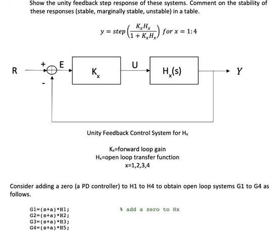
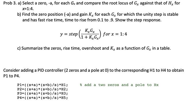
Show the unity feedback step response of these systems. Comment on the stability of these responses (stable, marginally stable, unstable) in a table. K,H, y = step 1+ K.H.) for x = 1:4 E U R K. H,(s) Y Unity Feedback Control System for H, K.=forward loop gain H=open loop transfer function x=1,2,3,4 Consider adding a zero (a PD controller) to H1 to H4 to obtain open loop systems G1 to G4 as follows. * add a zero to Hx G1=(s+a) *Hl; G2-(s+a) *H2; G3=(sta) *H3; G4=(s+a)*H5; Prob 3. a) Select a zero, -a, for each Gx and compare the root locus of Gy against that of H, for x=1:4. b) Find the zero position (-a) and gain K for each G, for which the unity step is stable and has fast rise time, time to rise from 0.1 to .9. Show the step response. y = step for x = 1:4 A1+ K,Gx. c) Summarize the zeros, rise time, overshoot and K, as a function of Gy in a table. Consider adding a PID controller (2 zeros and a pole at 0) to the corresponding H1 to H4 to obtain P1 to P4. P1= ( (s+a)*(s+b)/s) *H1; P2=( (sta)*(s+b)/s) *H2; P3=( (sta)* (s+b)/s) *H3; P4=( (sta)*(s+b)/s) *H5; * add a two zeros and a pole to Hx
Step by Step Solution
3.45 Rating (158 Votes )
There are 3 Steps involved in it

Get step-by-step solutions from verified subject matter experts