

Question: Problem 4: (20 Points) Table 2 shows the state diagram for a Moore finite state machine that has two inputs r and y, one output
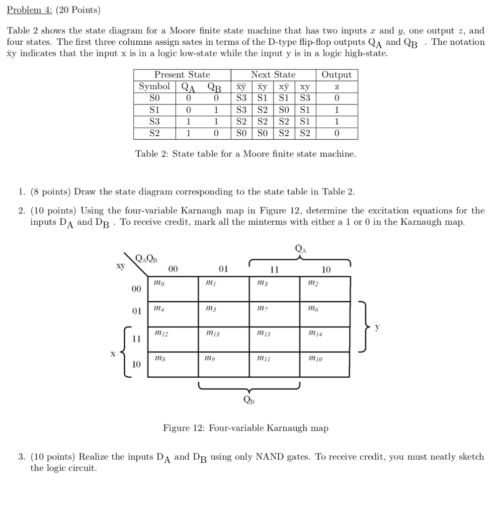
Problem 4: (20 Points) Table 2 shows the state diagram for a Moore finite state machine that has two inputs r and y, one output z, and four states. The first three columns assign sates in terms of the D-type flip-flop outputs QA and QB . The notation xy indicates that the input x is in a logic low-state while the input y is in a logic high-state. Present State Next State Output Symbol QA QRXyXyxy xyz 0 0 S3 S1 S1 S:3 SO S1 S3 S2 1S2 S2 S2 S1 0 SO SO S2 S2 0 Table 2: State table for a Moore finite state machine 1. (8 points) Draw the state diagram corresponding to the state table in Table 2 2. (10 points) Using the four-variable Karnaugh map in Figure 12, determine the excitation equations for the inputs DA and DB . To receive credit, mark all the minterms with either a 1 or 0 in the Karnaugh map Q.QB XV 01 n1 nm m6 01 1m4 n5 1112 m13 m15 m14 ms m9 m11 m10 10 Figure 12: Four-variable Karnaugh map 3. (10 points) Realize the inputs DA and Dp using only NAND gates. To receive credit, you must neatly sketch the logic circuit
Step by Step Solution
There are 3 Steps involved in it

Get step-by-step solutions from verified subject matter experts