

Question: Problem 5 Decoder Truth Table Logic circuit Truth Table The logic circuit above consists of three logic gates, a multiplexer, and a decoder. The inputs
Problem
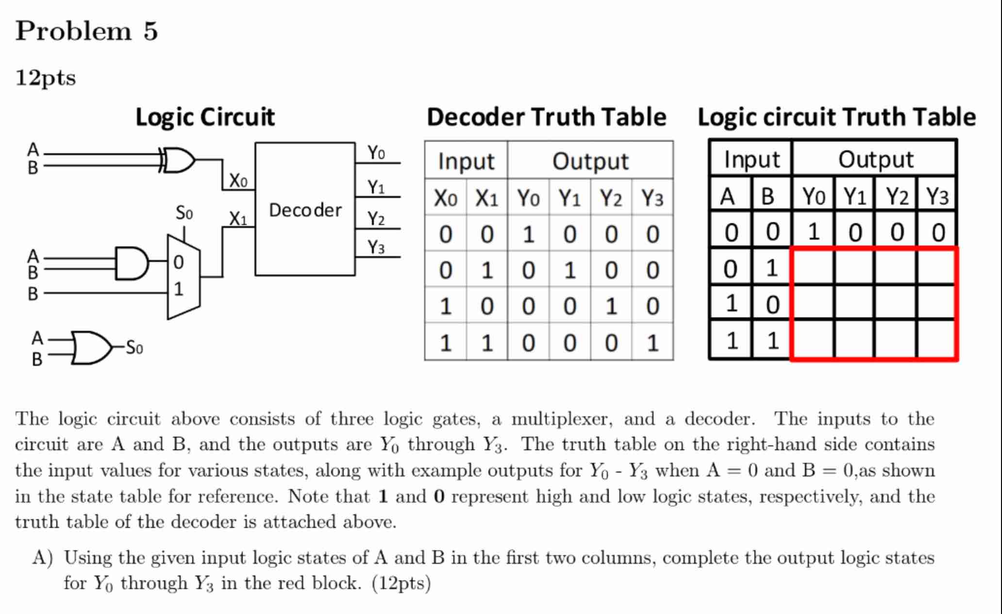
Decoder Truth Table
Logic circuit Truth Table
The logic circuit above consists of three logic gates, a multiplexer, and a decoder. The inputs to the circuit are A and B and the outputs are Y through Y The truth table on the righthand side contains the input values for various states, along with example outputs for YY when mathrmA and mathrmBas shown in the state table for reference. Note that mathbf and mathbf represent high and low logic states, respectively, and the truth table of the decoder is attached above.
A Using the given input logic states of A and B in the first two columns, complete the output logic states for Y through Y in the red block. pts
Step by Step Solution
There are 3 Steps involved in it
1 Expert Approved Answer
Step: 1 Unlock

Question Has Been Solved by an Expert!
Get step-by-step solutions from verified subject matter experts
Step: 2 Unlock
Step: 3 Unlock