

Question: Problem B - 4 - 1 2 Consider the mechanical system shown in Figure 4 - 5 9 . The system is initially at rest.
Problem B
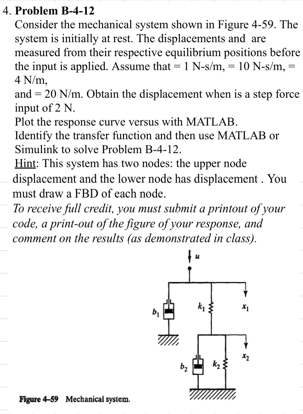
Consider the mechanical system shown in Figure The
system is initially at rest. The displacements and are
measured from their respective equilibrium positions before
the input is applied. Assume that
and Obtain the displacement when is a step force
input of N
Plot the response curve versus with MATLAB.
Identify the transfer function and then use MATLAB or
Simulink to solve Problem B
Hint: This system has two nodes: the upper node
displacement and the lower node has displacement. You
must draw a FBD of each node.
To receive full credit, you must submit a printout of your
code, a printout of the figure of your response, and
comment on the results as demonstrated in class
Step by Step Solution
There are 3 Steps involved in it
1 Expert Approved Answer
Step: 1 Unlock

Question Has Been Solved by an Expert!
Get step-by-step solutions from verified subject matter experts
Step: 2 Unlock
Step: 3 Unlock