

Question: Q . 2 ( a ) . Generate a steady - state problem of fluid flow over a 2 - Dimensional square using ANSYS fluid
Qa
Generate a steadystate problem of fluid flow over a Dimensional square using ANSYS fluid flow Fluent Present a the mesh of the problem b the number of nodes and elements you can see these directly from the statistics heading under the 'details of Mesh' when 'mesh' option is selected in the outline treec velocity magnitude contours, d Static and dynamic pressure contours, e Streamlines, and f velocity magnitude vectors over the square in the fluid domain. Use the following model parameters:
Geometry
a Select D geometry as the analysis type in the properties of the design modeler before entering the Design modeler
b The units should be set to centimeters.
c The square dimensions should be selected according to the student ID in the table below.
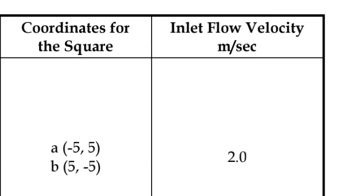
d The fluid domain should be with the following coordinates and
e While using the named section option for the square edges to name it 'square', keep the edge selection enabled in the top menu and with left mouse, click the edges one by one while keeping the ctrl key on the keyboard pressed.
Mesh
a The units should be changed to cm Mesh element shape should be taken as triangle this can be selected by inserting the method option from the mesh in the outline tree
b Square edge element size should be cm Keep the edge selection enabled in the top menu and with left mouse, click the edges one by one while keeping the ctrl key on the keyboard pressed.
c Number of mesh layers around the square should be the mesh layers can be added around the square by inserting the inflation option from the mesh in the outline tree. Keep the edge selection enabled in the top menu and with left mouse, click the edges one by one while keeping the ctrl key on the keyboard pressed Select inflation option as "first layer thicknessheight Put first layer height The growth rate should be
d Outside the inflation region, set the max. face size Element Sizeyou have to left click once on the mesh option in the outline tree and in the detailed menu below, enter the max. face size Element Size
Boundary conditions
a Gravity option should be enabled with the standard g value.
b Water should be taken as the fluid.
c Flow should be laminar.
d Water inlet velocity should be selected based on the table below. Each student should select the inlet flow velocity from the table against his ID
Solution
a Keep initialization to "hybrid".
Select iterations and reporting interval to
Paste all the results with discussion of the results in a word file, convert into PDF and then upload the file on Blackboard in the link provided inside the link "Assessments".
Note: Show the results and discussion as part of the solution
points
Qb
Run the same model for transient flow. Run the simulation for sec Then obtain and show the results cf for the transient case. Compare both the results steadystate and transient with discussion.
tabletableCoordinates forthe SquaretableInlet Flow Velocitymseca
Step by Step Solution
There are 3 Steps involved in it
1 Expert Approved Answer
Step: 1 Unlock

Question Has Been Solved by an Expert!
Get step-by-step solutions from verified subject matter experts
Step: 2 Unlock
Step: 3 Unlock