

Question: Question 4: 4-bit Shift Register using DFFs Design a 4-bit shift register using four DFFs (74LS74). The circuit should have one input called In, and
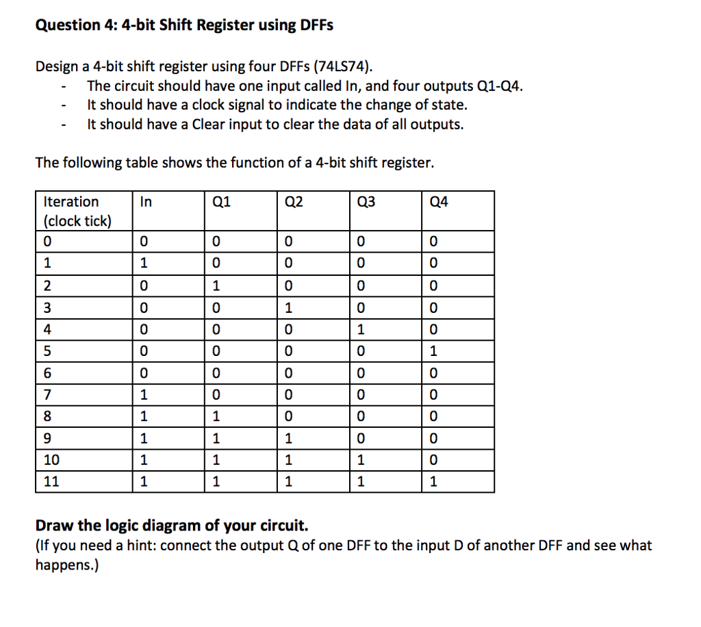
Question 4: 4-bit Shift Register using DFFs Design a 4-bit shift register using four DFFs (74LS74). The circuit should have one input called In, and four outputs Q1-Q4. - It should have a clock signal to indicate the change of state. It should have a clear input to clear the data of all outputs. The following table shows the function of a 4-bit shift register. Q1 Q2 Q3 Q4 Iteration (clock tick) 0 0 0 1 0 0 0 0 0 0 Non Pw 1 0 o Polololololololololol 0 0 1 PEP Poo 10 PTE | | 11 Draw the logic diagram of your circuit. (If you need a hint: connect the output Q of one DFF to the input D of another DFF and see what happens.)
Step by Step Solution
There are 3 Steps involved in it
1 Expert Approved Answer
Step: 1 Unlock

Question Has Been Solved by an Expert!
Get step-by-step solutions from verified subject matter experts
Step: 2 Unlock
Step: 3 Unlock