

Question: The T - beam shown in Fig. Loads: g = 2 0 k N m and q = 1 5 k N m Materials: C
The Tbeam shown in Fig.
Loads: and
Materials: C and Slongitudinal bars and stirrups
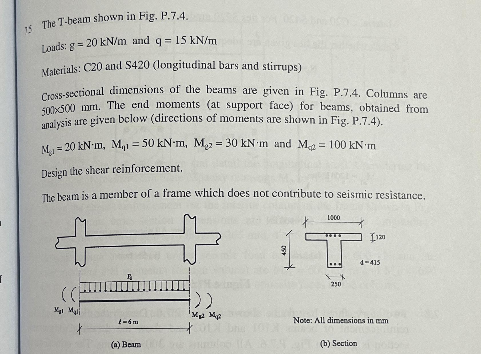
Crosssectional dimensions of the beams are given in Fig. Columns are The end moments at support face for beams, obtained from analysis are given below directions of moments are shown in Fig.
and
Design the shear reinforcement.
The beam is a member of a frame which does not contribute to seismic resistance.
Note: All dimensions in
Step by Step Solution
There are 3 Steps involved in it
1 Expert Approved Answer
Step: 1 Unlock

Question Has Been Solved by an Expert!
Get step-by-step solutions from verified subject matter experts
Step: 2 Unlock
Step: 3 Unlock