

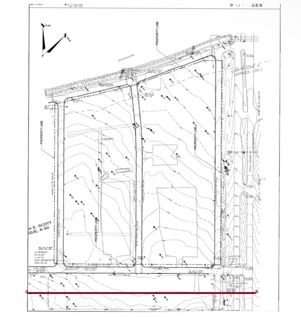
Question: Using the contour map provided, to lay out the vertical alignment, determine existing ground vertical alignment elevations and minimum length of the vertical curve. The
Using the contour map provided, to lay out the vertical alignment, determine existing ground vertical alignment elevations and minimum length of the vertical curve. The length of any vertical curve is governed by sight distance requirements.Consistent with design standards and objectives, minimize cuts and fills. Insofar as is possible, adhere to the general controls for vertical alignment. Tie to the given elevation and grade at Point A and B Your profile drawing should show the percent grade for all tangents. For each vertical curve, show the station PVC PVT and length of vertical curve, and provide a mass diagram. The following assumptions are given.
Design speed: mih
The deceleration rate for braking: ftsecPerceptionreaction time: sec
For this task, make sure to include elevationstation line graphs for the orginal vertical alignment and for your proposed vertical alignment Then use the information to create a mass diagram volumestation # chart from the orginal and proposed graphs and information. Be sure to Also include a cutfill chart for the information.
Step by Step Solution
There are 3 Steps involved in it
1 Expert Approved Answer
Step: 1 Unlock

Question Has Been Solved by an Expert!
Get step-by-step solutions from verified subject matter experts
Step: 2 Unlock
Step: 3 Unlock