

Question: Verilog code Your task is to implement ripple carry and carry lookahead versions of a 13-bit adder/subtractor using Verilog HD. The carry lookahead adder/subtractor must
Verilog code
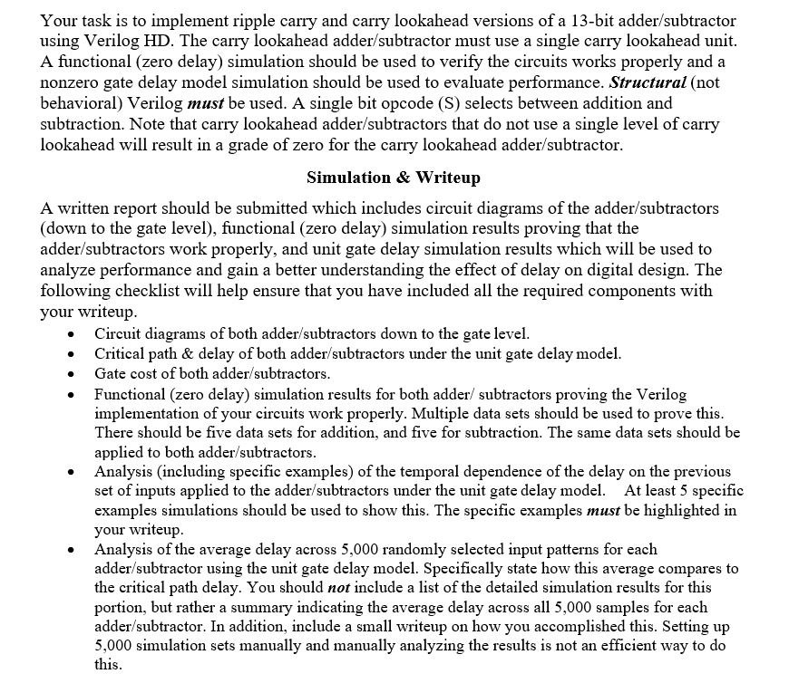
Your task is to implement ripple carry and carry lookahead versions of a 13-bit adder/subtractor using Verilog HD. The carry lookahead adder/subtractor must use a single carry lookahead unit. A functional (zero delay) simulation should be used to verify the circuits works properly and a nonzero gate delay model simulation should be used to evaluate performance. Structural (not behavioral) Verilog must be used. A single bit opcode (S) selects between addition and subtraction. Note that carry lookahead adder/subtractors that do not use a single level of carry lookahead will result in a grade of zero for the carry lookahead adder/subtractor Simulation & Writeup A written report should be submitted which includes circuit diagrams of the adder/subtractors (down to the gate level), functional (zero delay) simulation results proving that the adder/subtractors work properly, and unit gate delay simulation results which will be used to analyze performance and gain a better understanding the effect of delay on digital design. The following checklist will help ensure that you have included all the required components with your writeup Circuit diagrams of both adder/subtractors down to the gate level Critical path & delay of both adder/subtractors under the unit gate delay model . Gate cost of both adder/subtractors Functional (zero delay) simulation results for both adder/ subtractors proving the Verilog implementation of your circuits work properly. Multiple data sets should be used to prove this There should be five data sets for addition, and five for subtraction. The same data sets should be applied to both adder/subtractors Analysis (including specific examples) of the temporal dependence of the delay on the previous set of inputs applied to the adder/subtractors under the unit gate delay model. At least 5 specific examples simulations should be used to show this. The specific examples must be highlighted in your writeup Analysis of the average delay across 5,000 randomly selected input patterns for each adder/subtractor using the unit gate delay model. Specifically state how this average compares to the critical path delay. You should not include a list of the detailed simulation results for this portion, but rather a summary indicating the average delay across all 5,000 samples for each adder/subtractor. In addition, include a small writeup on how you accomplished this. Setting up 5,000 simulation sets manually and manually analyzing the results is not an efficient way to deo this . Your task is to implement ripple carry and carry lookahead versions of a 13-bit adder/subtractor using Verilog HD. The carry lookahead adder/subtractor must use a single carry lookahead unit. A functional (zero delay) simulation should be used to verify the circuits works properly and a nonzero gate delay model simulation should be used to evaluate performance. Structural (not behavioral) Verilog must be used. A single bit opcode (S) selects between addition and subtraction. Note that carry lookahead adder/subtractors that do not use a single level of carry lookahead will result in a grade of zero for the carry lookahead adder/subtractor Simulation & Writeup A written report should be submitted which includes circuit diagrams of the adder/subtractors (down to the gate level), functional (zero delay) simulation results proving that the adder/subtractors work properly, and unit gate delay simulation results which will be used to analyze performance and gain a better understanding the effect of delay on digital design. The following checklist will help ensure that you have included all the required components with your writeup Circuit diagrams of both adder/subtractors down to the gate level Critical path & delay of both adder/subtractors under the unit gate delay model . Gate cost of both adder/subtractors Functional (zero delay) simulation results for both adder/ subtractors proving the Verilog implementation of your circuits work properly. Multiple data sets should be used to prove this There should be five data sets for addition, and five for subtraction. The same data sets should be applied to both adder/subtractors Analysis (including specific examples) of the temporal dependence of the delay on the previous set of inputs applied to the adder/subtractors under the unit gate delay model. At least 5 specific examples simulations should be used to show this. The specific examples must be highlighted in your writeup Analysis of the average delay across 5,000 randomly selected input patterns for each adder/subtractor using the unit gate delay model. Specifically state how this average compares to the critical path delay. You should not include a list of the detailed simulation results for this portion, but rather a summary indicating the average delay across all 5,000 samples for each adder/subtractor. In addition, include a small writeup on how you accomplished this. Setting up 5,000 simulation sets manually and manually analyzing the results is not an efficient way to deo this
Step by Step Solution
There are 3 Steps involved in it

Get step-by-step solutions from verified subject matter experts