

A Peltier generator is made up of two thermoelectric elements connected in series (Fig. 11.13). One side
Question:
A Peltier generator is made up of two thermoelectric elements connected in series (Fig. 11.13). One side of the Peltier generator is maintained at temperature T+ and the other temperature T−. The electric current I generated by the Peltier generator flows through the thermoelectric materials labelled 1 and 2. The plate which is heated up to temperature T+ connects electrically these two materials but is not electrically available to the user. Its electric potential is V+. The other ends of the thermoelectric materials are on the cold side, at a temperature T−. They are connected to the electric leads of the device. A load resistance R0 is connected to these leads. The voltage V designates the electric potential difference between the leads. Analyse the operation of this generator using the electric charge and heat transport equations,
Fig 11.3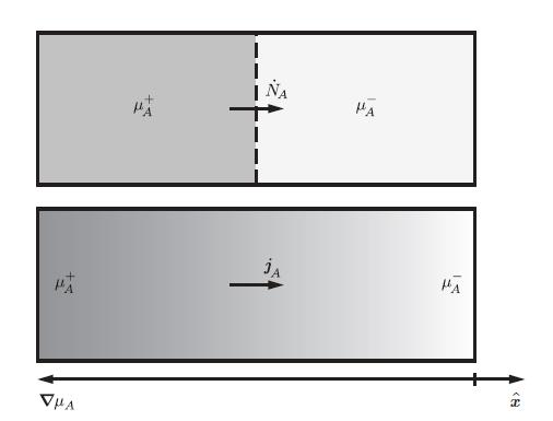
The thermoelectric materials 1 and 2 have a length d and a cross-section surface area A, which can be written as,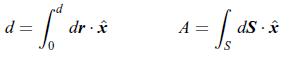 where ˆx is a unit vector oriented clockwise along the electric current density jq, and the infinitesimal length and surface vectors dr and dS are oriented in the same direction. The temperature difference between the hot and cold ends is given by,
 A Peltier generator has a load represented by the resistance R0 connected to its leads. V is the voltage between the leads. The electric bridge at V+ is not accessible to the user. The regions marked 1 and 2 represent the two thermoelectric materials. The regions marked T+ and T− are the hot and cold sides of the device.
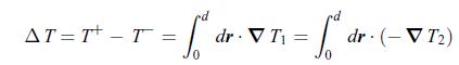 Likewise, the electric potential differences Δφ 1 and Δφ 2 between the hot and cold ends are written as,
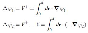 The electric charge conservation implies that the electric current densities are the same in each material, i.e. jq1 = jq2 . The electric current I flowing through materials 1 and 2 is the integral of the electric current densities jq1 and jq2 over the cross-section area A,
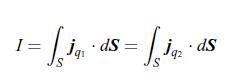 According to the relation (10.104), the thermal powers PQ1 and PQ2 are the integrals of the heat current densities jQ1 and jQ2 flowing through materials 1 and 2 over the cross-section area A,
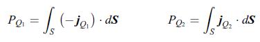
Determine
a) the thermal power P'Q applied on the hot side of the device when no electric current flows through the device.b) the effective electric resistance R of the two thermoelectric materials when the temperatures are equal, i.e. T+ = T−, and no electric current flows throughthe resistance R0, i.e. when R0 = ∞. Instead, an electric current flows through the thermoelectric materials.c) the electric current I as a function of the temperature difference ΔT.d) the thermodynamic efficiency of the generator defined as,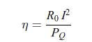 where here, PQ is the thermal power at the hot side when the electric current is flowing through the device. Show that the optimum load resistance is given by
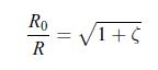 where ζ is a dimensionless parameter given by [188],
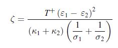
Step by Step Answer:


Principles Of Thermodynamics
ISBN: 9781108426091
1st Edition
Authors: Jean-Philippe Ansermet, Sylvain D. Brechet
