New Semester
Started
Get
50% OFF
Study Help!
--h --m --s
Claim Now
Question Answers
Textbooks
Find textbooks, questions and answers
Oops, something went wrong!
Change your search query and then try again
S
Books
FREE
Study Help
Expert Questions
Accounting
General Management
Mathematics
Finance
Organizational Behaviour
Law
Physics
Operating System
Management Leadership
Sociology
Programming
Marketing
Database
Computer Network
Economics
Textbooks Solutions
Accounting
Managerial Accounting
Management Leadership
Cost Accounting
Statistics
Business Law
Corporate Finance
Finance
Economics
Auditing
Tutors
Online Tutors
Find a Tutor
Hire a Tutor
Become a Tutor
AI Tutor
AI Study Planner
NEW
Sell Books
Search
Search
Sign In
Register
study help
engineering
civil engineering
Engineering Mechanics Statics 11 Edition Russell C. Hibbeler - Solutions
The compound shears are used to cut metal parts. Determine the vertical cutting force exerted on the rod R if a force F is applied at the grip G. The lobe CDE is in smooth contact with the head of the shear blade at E.Given:F = 20 lb a = 1.4 ft b = 0.2 ftc = 2 ft d = 0.75 ft e =
The handle of the sector press is fixed to gear G, which in turn is in mesh with the sector gear C. Note that AB is pinned at its ends to gear C and the underside of the table EF, which is allowed to move vertically due to the smooth guides at E and F. If the gears exert tangential forces between
The mechanism is used to hide kitchen appliances under a cabinet by allowing the shelf to rotate downward. If the mixer has weight W, is centered on the shelf, and has a mass center at G, determine the stretch in the spring necessary to hold the shelf in the equilibrium position shown. There is a
If each of the three links of the mechanism has a weight W, determine the angle θ for equilibrium. The spring, which always remains horizontal, is unstretched when θ = 0°.Given:W = 25 lbk = 60lb/fta = 4 ftb = 4 ft
Determine the required force P that must be applied at the blade of the pruning shears so that the blade exerts a normal force F on the twig at E.Given:F = 20 lba = 0.5 inb = 4 inc = 0.75 ind = 0.75 ine = 1 in
The three power lines exert the forces shown on the truss joints, which in turn are pin-connected to the poles AH and EG. Determine the force in the guy cable AI and the pin reaction at the support H.Units Used:kip = 103 lbGiven:F1 = 800 lb d = 125 ftF2 = 800 lb e = 50 fta = 40 ft f = 30 ftb = 20
The hydraulic crane is used to lift the load of weight W. Determine the force in the hydraulic cylinder AB and the force in links AC and AD when the load is held in the position shown.Units Used:kip = 103 lbGiven:W = 1400 lba = 8 ft c = 1 ftb = 7 ft γ = 70 deg
The kinetic sculpture requires that each of the three pinned beams be in perfect balance at all times during its slow motion. If each member has a uniform weight density γ and length L, determine the necessary counterweights W1, W2 and W3 which must be added to the ends of each member to keep the
The three-member frame is connected at its ends using ball-and-socket joints. Determine the x,y, z components of reaction at B and the tension in member ED. The force acting at D is F.Given:F = (135 200 -180) lba = 6 ft e = 3 ftb = 4 ft f = 1 ftd = 6 ft g = 2 ftc = g + f
The four-member "A" frame is supported at A and E by smooth collars and at G by a pin. All the other joints are ball-and-sockets. If the pin at G will fail when the resultant force there is Fmax, determine the largest vertical force P that can be supported by the frame. Also, what are the x, y, z
The structure is subjected to the loading shown. Member AD is supported by a cable AB and a roller at C and fits through a smooth circular hole at D. Member ED is supported by a roller at D and a pole that fits in a smooth snug circular hole at E. Determine the x, y, z components of reaction at E
The structure is subjected to the loadings shown. Member AB is supported by a ball-and-socket at A and smooth collar at B. Member CD is supported by a pin at C. Determine the x, y, z components of reaction at A and C.Given:a = 2 m M = 800 N ∙ mb = 1.5 m F = 250 Nc = 3 m θ1 = 60 degd = 4 m θ2 =
Determine the resultant forces at pins B and C on member ABC of the four-member frame.Given:w = 150 lb/fta = 5 ftb = 2 ftc = 2 fte = 4 ftd = a + b − c
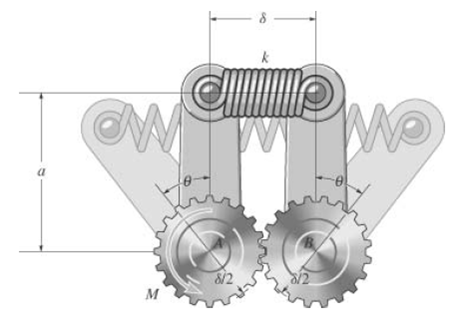
The mechanism consists of identical meshed gears A and B and arms which are fixed to the gears. The spring attached to the ends of the arms has an unstretched length δ and a stiffness k. If a torque M is applied to gear A, determine the angle θ through which each arm rotates. The gears are each
Determine the force in each member of the truss and state if the members are in tension or compression.Units Used:kN = 1000 NGiven:F1 = 20kNF2 = 10kNa = 1.5 mb = 2 m
The spring has an unstretched length δ. Determine the angle θ for equilibrium if the uniform links each have a mass mlink.Given:mlink = 5 kgδ = 0.3 mk = 400N/ma = 0.1 mb = 0.6 mg = 9.81m/s2
The spring has an unstretched length δ. Determine the mass mlink of each uniform link if the angle for equilibrium is θ.Given:δ = 0.3 mθ = 20 degk = 400N/ma = 0.1 mb = 0.6 mg = 9.81m/s2
Determine the horizontal and vertical components of force that the pins A and B exert on the two-member frame.Given:w = 400 N/ma = 1.5 mb = 1 mc = 1 mF = 0 Nθ = 60 deg
Determine the horizontal and vertical components of force that the pins A and B exert on the two-member frame.Given:w = 400N/ma = 1.5 mb = 1 mc = 1 mF = 500 Nθ = 60 deg
Determine the force in each member of the truss and indicate whether the members are in tension or compression.Units Used:kip = 1000 lbGiven:F1 = 1000 lb F2 = 500 lb a = 4 ftb = 8 ftc = 4 ft
Determine the force in each member of the truss and state if the members are in tension or compression.Units Used:kip = 103 lbGiven:F = 1000 lba = 10 ftb = 10 ft
The column is fixed to the floor and is subjected to the loads shown. Determine the internal normal force, shear force, and moment at points A and B.Units Used:kN = 103 NGiven:F1 = 6kNF2 = 6kNF3 = 8kNa = 150 mmb = 150 mmc = 150 mm
The axial forces act on the shaft as shown. Determine the internal normal forces at points A and B.Given:F1 = 20 lbF2 = 50 lbF3 = 10 lb
The shaft is supported by smooth bearings at A and B and subjected to the torques shown.Determine the internal torque at points C, D, and E.Given:M1 = 400 N ∙ mM2 = 150 N ∙ mM3 = 550 N ∙ m
Three torques act on the shaft. Determine the internal torque at points A, B, C, and D.Given:M1 = 300 N ∙ mM2 = 400 N ∙ mM3 = 200 N ∙ m
The shaft is supported by a journal bearing at A and a thrust bearing at B. Determine the normal force, shear force, and moment at a section passing through(a) Point C, which is just to the right of the bearing at A, and(b) Point D, which is just to the left of the force F2.Units Used:kip = 103
Determine the internal normal force, shear force, and moment at point C.Given:M = 400 lb⋅ fta = 4 ftb = 12 ft
Determine the internal normal force, shear force, and moment at point C.Units Used:kN = 103 NGiven:F1 = 30 kNF2 = 50 kNF3 = 25 kNa = 1.5 mb = 3 mθ = 30 deg
Determine the normal force, shear force, and moment at a section passing through point C. Assume the support at A can be approximated by a pin and B as a roller.Units used:kip = 103 lbGiven:F1 = 10 kip a = 6 ftF2 = 8 kip b = 12 ftw = 0.8kip/ftc = 12 ftd = 6 ft
The beam AB will fail if the maximum internal moment at D reaches Mmax or the normal force in member BC becomes Pmax. Determine the largest load w it can support.Given:Mmax = 800 N ∙ mPmax = 1500 Na = 4 mb = 4 mc = 4 md = 3 m
Determine the shear force and moment acting at a section passing through point C in the beam.Units Used:kip = 103 lbGiven:w = 3kip/fta = 6 ftb = 18 ft
Determine the internal normal force, shear force, and moment at points E and D of the compound beam.Given:M = 200 N ∙ m c = 4 mF = 800 N d = 2 ma = 2 m e = 2 mb = 2 m
The boom DF of the jib crane and the column DE has a uniform weight density γ. If the hoist and load have weight W, determine the normal force, shear force, and moment in the crane at sections passing through points A, B, and C. Treat the boom tip, beyond the hoist, as weightless.Given:W = 300
Determine the internal normal force, shear force, and moment at point C.Units Used:kip = 103 lbGiven:a = 0.5 ft d = 8ftb = 2 ft e = 4 ftc = 3 ft w = 150lb/ft
Determine the normal force, shear force, and moment at a section passing through point D of the two-member frame.Units Used:kN = 103 NGiven:w = 400N/ma = 2.5 mb = 3 mc = 6 m
The beam has weight density γ. Determine the internal normal force, shear force, and moment at point C.Units Used:kip = 103 lbGiven:γ = 280lb/fta = 3 ftb = 7 ftc = 8 ftd = 6 ft
Determine the internal normal force, shear force, and moment at points C and D of the beam.Units Used:kip = 103 lbGiven:w1 = 60lb/ft w2 = 40lb/ftF = 690 lba = 12 ftb = 15 ftc = 10 ftd = 5 fte = 12 f = 5
Determine the normal force, shear force, and moment acting at a section passing through point C. Units Used: kip = 103 lbGiven:F1 = 800 lbF2 = 700 lbF3 = 600 lbθ = 30 dega = 1.5 ftb = 1.5 ftc = 3 ftd = 2 fte = 1 ftf = a +b + c − d − e
Determine the normal force, shear force, and moment acting at a section passing through point D.Units Used: kip = 103 lbGiven:F1 = 800 lbF2 = 700 lbF3 = 600 lbθ = 30 dega = 1.5 ftb = 1.5 ftc = 3 ftd = 2 fte = 1 ftf = a + b + c − d − e
Determine the normal force, shear force, and moment at a section passing through point C.Units Used:kN = 103 NGiven:P = 8 kN c = 0.75 ma = 0.75m d = 0.5 mb = 0.75m r = 0.1 m
The cable will fail when subjected to a tension Tmax. Determine the largest vertical load P the frame will support and calculate the internal normal force, shear force, and moment at a section passing through point C for this loading.Units Used:kN = 103 NGiven:Tmax = 2kNa = 0.75 mb = 0.75 mc = 0.75
Determine the internal shear force and moment acting at point C of the beam.Units Used:kip = 103 lbGiven:w = 2kip/fta = 9 ft
Determine the internal shear force and moment acting at point D of the beam.Units Used:kip = 103 lbGiven:w = 2kip/fta = 6 ftb = 9 ft
The shaft is supported by a journal bearing at A and a thrust bearing at B. Determine the internal normal force, shear force, and moment at(a) Point C, which is just to the right of the bearing at A, and(b) Point D, which is just to the left of the F2 force.Units Used:kip = 103 lbGiven:F1 = 2500 lb
The jack AB is used to straighten the bent beam DE using the arrangement shown. If the axial compressive force in the jack is P, determine the internal moment developed at point C of the top beam. Neglect the weight of the beams.Units Used:kip = 103 lbGiven:P = 5000 lba = 2 ftb = 10 ft
The jack AB is used to straighten the bent beam DE using the arrangement shown.If the axial compressive force in the jack is P, determine the internal moment developed at point C of the top beam. Assume that each beam has a uniform weight density γ.Units Used:kip = 103 lbGiven:P = 5000 lbγ =
Determine the normal force, shear force, and moment in the beam at sections passing through points D and E. Point E is just to the right of the F load.Units Used:kip = 103 lbGiven: a = 6 ftw = 1.5kip/ft b = 6 ftc = 4 ftF = 3 kipd = 4 ft
Determine the normal force, shear force, and moment at a section passing through point D of the two-member frame.Units Used:kN = 103 NGiven:w1 = 200N/mw2 = 400N/ma = 2.5 mb = 3 mc = 6 m
Determine the normal force, shear force, and moment at sections passing through points E and F. Member BC is pinned at B and there is a smooth slot in it at C. The pin at C is fixed to member CD. Units Used: kip = 103 lb Given: M = 350 lb ∙ ft w = 80lb/ft c = 2 ft F = 500 lb d = 3 ftθ = 60 deg e
The bolt shank is subjected to a tension F. Determine the internal normal force, shear force, and moment at point C.Given:F = 80 lba = 6 in
Determine the normal force, shear force, and moment acting at sections passing through points B and C on the curved rod. Units Used: kip = 103 lb Given: F1 = 300 lb θ = 30 deg r = 2 ft F2 = 400 lb φ = 45 deg
The cantilevered rack is used to support each end of a smooth pipe that has total weight W. Determine the normal force, shear force, and moment that act in the arm at its fixed support A along a vertical section.Units Used:kip = 103 lbGiven:W = 300 lbr = 6 inθ = 30 deg
Determine the normal force, shear force, and moment at a section passing through point D of the two-member frame.Units Used:kN = 103 NGiven:w = 0.75kN/mF = 4 kNa = 1.5 m d = 1.5 mb = 1.5 m e = 3c = 2.5 m f = 4
Determine the internal normal force, shear force, and moment acting at point A of the smooth hook.Given:θ = 45 dega = 2 inF = 20 lb
Determine the internal normal force, shear force, and moment acting at points B and C on the curved rod.Units Used:kip = 103 lbGiven:F = 500 lb θ 2 = 30 degr = 2 ft a = 3θ1 = 45 deg b = 4
Determine the ratio a/b for which the shear force will be zero at the midpoint C of the beam.
The semicircular arch is subjected to a uniform distributed load along its axis of w0 per unit length.Determine the internal normal force, shear force, and moment in the arch at angle θ.Given:θ = 45 deg
The semicircular arch is subjected to a uniform distributed load along its axis of w0 per unit length. Determine the internal normal force, shear force, and moment in the arch at angle θ.Given:θ = 120 deg
Determine the x, y, z components of internal loading at a section passing through point C in the pipe assembly. Neglect the weight of the pipe.Units Used:kip = 103 lbF1 = (0 350 -400) lbF2 = (150 0 -300) lba = 1.5 ft b = 2 ft c = 3 ft
Determine the x, y, z components of internal loading at a section passing through point C in the pipe assembly. Neglect the weight of the pipe.Units Used:kip = 103 lbGiven:F1 = (-80 200 -300) lbF2 = (250 -150 -200) lba = 1.5 ft b = 2 ft c = 3 ft
Determine the x, y, z components of internal loading in the rod at point D.Units Used:kN = 103 NGiven:M = 3kN ∙ mF = (7 -12 -5) kNa = 0.75 mb = 0.2 mc = 0.2 md = 0.6 me = 1 m
Determine the x, y, z components of internal loading in the rod at point E.Units Used:kN = 103 NGiven:M = 3kN ∙ mF = (7 -12 -5) kNa = 0.75 mb = 0.4 mc = 0.6 md = 0.5 me = 0.5 m
Draw the shear and moment diagrams for the shaft in terms of the parameters shown; there is a thrust bearing at A and a journal bearing at B.Units Used:kN = 103 NGiven:P = 9kNa = 2 mL = 6 m
Draw the shear and moment diagrams for the beam in terms of the parameters shown.Given:P = 800 lb a = 5 ft L = 12 ft
Draw the shear and moment diagrams for the beam?(a) In terms of the parameters shown;(b) Set M0 and L as given.Given:M0 = 500 N ∙ mL = 8 m
The beam will fail when the maximum shear force is Vmax or the maximum bending moment is Mmax. Determine the magnitude M0 of the largest couple moments it will support.Units Used:kN = 103 NGiven:L = 9 mVmax = 5kNMmax = 2kN ∙ m
The shaft is supported by a thrust bearing at A and a journal bearing at B. Draw the shear and moment diagrams for the shaft in terms of the parameters shown.Given:w = 500lb/ftL = 10 ft
The shaft is supported by a thrust bearing at A and a journal bearing at B. The shaft will fail when the maximum moment is Mmax. Determine the largest uniformly distributed load w the shaft will support.Units Used:kip = 103 lbGiven:L = 10 ftMmax = 5 kip ∙ ft
Draw the shear and moment diagrams for the beam.Units Used: kN = 103 NGiven:w = 2 kN/mL = 5 mMB = 5kN ∙ m
Draw the shear and moment diagrams for the beam.Units Used: kN = 103 NGiven:w = 3 kN/m F = 10kNL = 6 m
Draw the shear and moment diagrams for the beam.Units Used:kN = 103 NGiven:a = 2 m b = 4 m = w 1.5kN/m
Draw the shear and moment diagrams for the beam.Given:L = 20 ft w = 250lb/ftM1 = 150 lb⋅ ft M2 = 150 lb⋅ ft
Draw the shear and moment diagrams for the beam.Units Used:kN = 103 NGiven:w = 40kN/m F = 20kN M = 150kN ∙ m a = 8 m b = 3 m
Draw the shear and moment diagrams for the beam.
Draw the shear and bending-moment diagrams for beam ABC. Note that there is a pin at B.
The beam has depth a and is subjected to a uniform distributed loading w which acts at an angle θ from the vertical as shown. Determine the internal normal force, shear force, and moment in the beam as a function of x.Given:a = 2 ftL = 10 ftθ = 30 degw = 50 lb/ft
Draw the shear and moment diagrams for the beam. Given: w = 250lb/ft L = 12 ft
The beam will fail when the maximum shear force is Vmax or the maximum moment is Mmax.Determine the largest intensity w of the distributed loading it will support.Given:L = 18 ftVmax = 800 lbMmax = 1200 lb ∙ ft
The beam will fail when the maximum internal moment is Mmax. Determine the position x of the concentrated force P and its smallest magnitude that will cause failure.
Draw the shear and moment diagrams for the beam.Given:w = 30lb/ft MC = 180 lb ∙ fta = 9 ft b = 4.5 ft
The cantilevered beam is made of material having a specific weight γ. Determine the shear and moment in the beam as a function of x.
Draw the shear and moment diagrams for the beam.Given: kip = 103 lbw1 = 30lb/ft w2 120lb/ftL = 12 ft
Draw the shear and moment diagrams for the beam.Units Used:kip = 103 lbGiven:F1 = 20 kip F2 = 20 kip w = 4 kip/ft a = 15 ft b = 30 ft c = 15 ft
Express the x, y, z components of internal loading in the rod at the specific value for y, where 0 Units Used:kip = 103 lbGiven: y = 2.5 ftw = 800lb/ft F = 1500 lba = 4 ft b = 2 ft
Determine the normal force, shear force, and moment in the curved rod as a function of θ.Given:c = 3d = 4
The quarter circular rod lies in the horizontal plane and supports a vertical force P at its end. Determine the magnitudes of the components of the internal shear force, moment, and torque acting in the rod as a function of the angle θ.
Draw the shear and moment diagrams for the beam.Given:MB = 800 lb⋅ ft F = 100 lb a = 5 ftb = 5 ft
Draw the shear and moment diagrams for the beam.Units Used: kN = 103 NGiven:w = 3kN/mF = 10kNL = 6 m
Draw the shear and moment diagrams for the beam.Units Used: kN = 103 NGiven: F = 7 kN M = 12 kN ∙ m a = 2 m b = 2 m c = 4 m
Draw the shear and moment diagrams for the beam.Units Used:kN = 103 NGiven:a = 2 m b = 4 m w = 1.5kN/m
Draw the shear and moment diagrams for the beam.Given:w = 30lb/ft MC = 180 lb⋅ fta = 9 ft b = 4.5 ft
Draw the shear and moment diagrams for the beam.Given: kip = 103 lbw1 = 30 lb/ftw2 = 120 lb/ftL = 12 ft
Draw the shear and moment diagrams for the shaft. The support at A is a journal bearing and at B it is a thrust bearing.Given:F1 = 400 lbF2 = 800 lbw = 100lb/in a = 4 in b = 12 in c = 4 in
Draw the shear and moment diagrams for the beam.A Units Used:kN = 103 NGiven:F1 = 10 kNF2 = 10 kN M0 = 12 kN ∙ ma = 2 m b = 2 m c = 2 m d = 2 m
Draw the shear and moment diagrams for the shaft. The support at A is a journal bearing and at B it is a thrust bearing.Given:F = 200 lb w = 100 lb/ft M = 300 lb⋅ ft a = 1 ft b = 4 ft c = 1 ft
Draw the shear and moment diagrams for the beam.Units Used:kN = 103 NGiven: F = 8kN M = 20kN ∙ m w = 15kN/m a = 2 m b = 1 m c = 2 m d = 3 m
Draw the shear and moment diagrams for the shaft. The support at A is a thrust bearing and at B it is a journal bearing.Units Used:kN = 103 NGiven: w = 2kN/m F = 4 kN a = 0.8 m b = 0.2 m
Draw the shear and moment diagrams for the beam.Given:w = 20lb/ft MB = 160 lb ft a = 20 ft b = 20 ft
Draw the shear and moment diagrams for the beam.Given:w = 20lb/ft MB = 160 lb ft a = 20 ft b = 20 ft
The beam consists of two segments pin connected at B. Draw the shear and moment diagrams for the beam.Given:F = 700 lb w = 150 lb/ft M = 800 lb ft a = 8 ft b = 4 ft c = 6 ft
Showing 600 - 700
of 2574
1
2
3
4
5
6
7
8
9
10
11
12
13
14
15
Last
Step by Step Answers
.PNG)
.PNG)
.PNG)
.PNG)
.PNG)
.PNG)
.PNG)
.PNG)
.PNG)
.PNG)
.PNG)
.PNG)
.PNG)
.PNG)
.PNG)
.PNG)
.PNG)
.PNG)
.PNG)
.PNG)
.PNG)
.PNG)
.PNG)
.PNG)
.PNG)
.PNG)
.PNG)
.PNG)
.PNG)
.PNG)
.PNG)
.PNG)
.PNG)
.PNG)
.PNG)
.PNG)
.PNG)
.PNG)
.PNG)
.PNG)
.PNG)
.PNG)
.PNG)
.PNG)
.PNG)
.PNG)
.PNG)
.PNG)
.PNG)
.PNG)
.PNG)
.PNG)
.PNG)
.PNG)
.PNG)
.PNG)
.PNG)
.PNG)
.PNG)
.PNG)
.PNG)
.PNG)
.PNG)
.PNG)
.PNG)
.PNG)
.PNG)
.PNG)
.PNG)
.PNG)
.PNG)
.PNG)
.PNG)
.PNG)
.PNG)
.PNG)
.PNG)
.PNG)
.PNG)
.PNG)
.PNG)
.PNG)
.PNG)
.PNG)
.PNG)
.PNG)
.PNG)
.PNG)
.PNG)
.PNG)
.PNG)
.PNG)
.PNG)
.PNG)
.PNG)
.PNG)
.PNG)

