New Semester
Started
Get
50% OFF
Study Help!
--h --m --s
Claim Now
Question Answers
Textbooks
Find textbooks, questions and answers
Oops, something went wrong!
Change your search query and then try again
S
Books
FREE
Study Help
Expert Questions
Accounting
General Management
Mathematics
Finance
Organizational Behaviour
Law
Physics
Operating System
Management Leadership
Sociology
Programming
Marketing
Database
Computer Network
Economics
Textbooks Solutions
Accounting
Managerial Accounting
Management Leadership
Cost Accounting
Statistics
Business Law
Corporate Finance
Finance
Economics
Auditing
Tutors
Online Tutors
Find a Tutor
Hire a Tutor
Become a Tutor
AI Tutor
AI Study Planner
NEW
Sell Books
Search
Search
Sign In
Register
study help
physics
electricity and magnetism
Fundamentals Of Electric Circuits 3rd Edition Matthew Sadiku, Charles Alexander - Solutions
Use PSpice to verify the results in Example 5.9. Assume nonideal op amps LM324.Example 5.9 - Determine vo and io in the op amp circuit in Fig. 5.30.Answer: 10 V, 1 mA.
Design a six bit digital to analog converter? (a) If |Vo| = 1.1875 V is desired, what should [V1V2V3V4V5V6] be? (b) Calculate |Vo| if [V1V2V3V4V5V6] = [011011]? (c) What is the maximum value |Vo| assume?
A four-bit R-2R ladder DAC is presented in Fig. 5.103.(a) Show that the output voltage is given by(b) If Rf = 12 kΩ and R = 10 kΩ, find |Vo| for [V1V2V3V4] = and [V1V2/V3V4] = [0101].
In the op amp circuit of Fig. 5.104, find the value of R so that the power absorbed by the 10-kΩ resistor is 10 mW. Take vs = 2V?
Assuming a gain of 200 for an IA, find its output voltage for: (a) v1 = 0.402 V and v2 = 0.386 V (b) v1 = 1.002 V and v2 = 1.011 V?
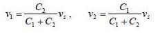
Figure 5.105 displays a two-op-amp instrumentation amplifier. Derive an expression for vo in terms of v1 and v2. How can this amplifier be used as a subtractor?
Figure 5.106 shows an instrumentation amplifier driven by a bridge. Obtain the gain vo/vi of the amplifier?
Determine vo for each of the op amp circuits in Fig. 5.48.
The op amp circuit in Fig. 5.107 is a current amplifier. Find the current gain io/is of the amplifier?
A non-inverting current amplifier is portrayed in Fig. 5.108. Calculate the gain io/is. Take R1 = 8 kΩ and R2 = 1 kΩ?
Refer to the bridge amplifier shown in Fig. 5.109. Determine the voltage gain vo/v1?
A voltage-to-current converter is shown in Fig. 5.110, which means that iL = Av1 if R1R2 = R3R4. Find the constant term A.
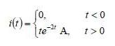
If the voltage across a 5-F capacitor is 2te-3t V, find the current and the power.
The voltage across a 2-mF capacitor is shown in Fig. 6.47. Determine the current through the capacitor.
A 4-mF capacitor has the current waveform shown in Fig. 6.48. Assuming that v(0)=10V, sketch the voltage waveform v(t).
A voltage of 6e-2000t V appears across a parallel combination of a 100-mF capacitor and a 12-Ω resistor. Calculate the power absorbed by the parallel combination.
Find the voltage across the capacitors in the circuit of Fig. 6.49 under dc conditions.
Series-connected 20-pF and 60-pF capacitors are placed in parallel with series-connected 30-pF and 70-pF capacitors. Determine the equivalent capacitance.
Two capacitors (20 μF and 30 μF) are connected to a 100-V source. Find the energy stored in each capacitor if they are connected in: (a) Parallel (b) Series
Determine the equivalent capacitance for each of the circuits in Fig. 6.51.(a) (b)
Find Ceq in the circuit of Fig. 6.52 if all capacitors are 4 μF
Find the equivalent capacitance between terminals a and b in the circuit of Fig. 6.53. All capacitances are in μF.
A 20-μF capacitor has energy w(t). 10cos2 377t J. Determine the current through the capacitor.
Find the equivalent capacitance at terminals a-b of the circuit in Fig. 6.54.
Determine the equivalent capacitance at terminals a - b of the circuit in Fig. 6.55.
Obtain the equivalent capacitance of the circuit in Fig. 6.56.
For the circuit in Fig. 6.57, determine:(a) The voltage across each capacitor,(b) The energy stored in each capacitor.
Repeat Prob. 6.23 for the circuit in Fig. 6.58.In Problem 6.23 (a) The voltage across each capacitor, (b) The energy stored in each capacitor.
(a) Show that the voltage-division rule for two capacitors in series as in Fig. 6.59(a) isassuming that the initial conditions are zero.(b) For two capacitors in parallel as in Fig. 6.59(b), show that the current-division rule isassuming that the initial conditions are zero.
Three capacitors, C1 = 5 μF, C2 = 10 μF, and C3 = 20 μF, are connected in parallel across a 150-V source. Determine: (a) The total capacitance, (b) The charge on each capacitor, (c) The total energy stored in the parallel combination.
Given that four 4-μF capacitors can be connected in series and in parallel, find the minimum and maximum values that can be obtained by such series/parallel combinations.
Obtain the equivalent capacitance of the network shown in Fig. 6.58.
Determine Ceq for each circuit in Fig. 6.61.(a)(b)
Assuming that the capacitors are initially uncharged, find vo(t) in the circuit in Fig. 6.62.
If v(0)=0, find v(t), i1(t), and i2(t) in the circuit in Fig. 6.63.
In the circuit in Fig. 6.64, let is = 30e-2t mA and v1(0) = 50 V, v2(0) = 20 V.Determine: (a) v1(t) and v2(t),(b) The energy in each capacitor at t = 0.5 s.
Obtain the Thèvenin equivalent at the terminals, a-b, of the circuit shown in Fig. 6.65. Please note that Thèvenin equivalent circuits do not generally exist for circuits involving capacitors and resistors. This is a special case where the Thèvenin equivalent
The current through a 10-mH inductor is 6e-t / 2 A. Find the voltage and the power at t = 3 s.
An inductor has a linear change in current from 50 mA to 100 mA in 2 ms and induces a voltage of 160 mV. Calculate the value of the inductor.
The current through a 12-mH inductor is i(t) = 30te-2t A, t ≥ 0. Determine: (a) The voltage across the inductor, (b) The power being delivered to the inductor at t = 1 s, (c) The energy stored in the inductor at t = 1 s.
The current through a 12-mH inductor is 4 sin 100t A. Find the voltage, and also the energy stored in the inductor for 0 < t < π/200 s.
The current through a 40-mH inductor isFind the voltage v(t).
The voltage across a 200-mH inductor is given by v(t) = 3t2 + 2t + 4 V for t > 0. Determine the current i(t) through the inductor. Assume that i(0) = 1 A.
A current of 6 sin 4t A flows through a 2-F capacitor. Find the voltage v(t) across the capacitor given that v(0) = 1 V.
The current through a 5-mH inductor is shown in Fig. 6.66. Determine the voltage across the inductor at t=1, 3, and 5ms.
The voltage across a 2-H inductor is 20(1 - e-2t) V. If the initial current through the inductor is 0.3 A, find the current and the energy stored in the inductor at t = 1 s.
If the voltage waveform in Fig. 6.67 is applied across the terminals of a 5-H inductor, calculate the current through the inductor. Assume i(0) = -1 A.
The current in an 80-mH inductor increases from 0 to 60 mA. How much energy is stored in the inductor?
A 100-mH inductor is connected in parallel with a 2-kΩ resistor. The current through the inductor is i(t) = 50e-400t mA. (a) Find the voltage vL across the inductor. (b) Find the voltage vR across the resistor. (c) Is VR(t) + VL (t) = 0? (d) Calculate the energy in the inductor at t = 0.
If the voltage waveform in Fig. 6.68 is applied to a 10-mH inductor, find the inductor current i(t). Assume i(0) = 0.
Find vC, iL, and the energy stored in the capacitor and inductor in the circuit of Fig. 6.69 under dc conditions.
For the circuit in Fig. 6.70, calculate the value of R that will make the energy stored in the capacitor the same as that stored in the inductor under dc conditions.
Under steady-state dc conditions, find i and v in the circuit in Fig. 6.71.
Find the equivalent inductance of the circuit in Fig. 6.72. Assume all inductors are 10 mH.
The voltage across a 4-μF capacitor is shown in Fig. 6.45. Find the current waveform.
An energy-storage network consists of series-connected 16-mH and 14-mH inductors in parallel with a series connected 24-mH and 36-mH inductors. Calculate the equivalent inductance.
Determine Leq at terminals a-b of the circuit in Fig. 6.73.
Find Leq in the circuit of Fig. 6.74.
Find Leq at the terminals of the circuit in Fig. 6.75.
Find the equivalent inductance looking into the terminals of the circuit in Fig. 6.76.
Find Leq in each of the circuits of Fig. 6.77.(a)(b)
Find Leq in the circuit in Fig. 6.78.
Determine the Leq that can be used to represent the inductive network of Fig. 6.79 at the terminals.
The current waveform in Fig. 6.80 flows through a 3-H inductor. Sketch the voltage across the inductor over the interval 0
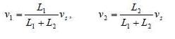
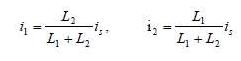
(a) For two inductors in series as in Fig. 6.81(a), show that the current-division principle isAssuming that the initial conditions are zero(b) For two inductors in parallel as in Fig. 6.81(b), show that the current-division principle isFigure 6.81
The voltage waveform in Fig. 6.46 is applied across a 30-μF capacitor. Draw the current waveform through it.
In the circuit of Fig. 6.82, io(0) = 2 A. Determine io(t) and vo(t) for t > 0.
Consider the circuit in Fig. 6.83. Find:(a) Leq, i1(t) and i2(t) if is = 3e-1 mA,(b) vo(t),(c) Energy stored in the 20-mH inductor at t=1s.
Consider the circuit in Fig. 6.84. Given that v(t) = 12e-3t mV for t > 0 andi1(0) = -10 mA, find:(a) i2(0),(b) i1(t) and i2(t).
In the circuit in Fig. 6.85, sketch vo.
The switch in Fig. 6.86 has been in position A for a long time. At t = 0, the switch moves from position A to B. The switch is a make-before-break type so that there is no interruption in the inductor current. Find:(a) i(t) for t > 0,(b) v just after the switch has been moved to position B,(c) v(t)
The inductors in Fig. 6.87 are initially charged and are connected to the black box at t = 0. If i1(0) = 4 A, i2(0) = -2 A, and v(t) = 50e-200t mV, t ‰¥ 0$, find:(a) The energy initially stored in each inductor,(b) The total energy delivered to the black box from t = 0 to t =
The current i(t) through a 20-mH inductor is equal, in magnitude, to the voltage across it for all values of time. If i(0) =2 A, find i(t).
An op amp integrator has R= 50 kΩ and C = 0.04 μF. If the input voltage is vi = 10 sin 50t mV, obtain the output voltage.
A 10-V dc voltage is applied to an integrator with R = 50 kΩ, C = 100 μF at t = 0. How long will it take for the op amp to saturate if the saturation voltages are +12 V and -12 V? Assume that the initial capacitor voltage was zero.
An op amp integrator with R = 4 MΩ and C = 1 μF has the input waveform shown in Fig. 6.88. Plot the output waveform.
At t=0, the voltage across a 50-mF capacitor is 10 V. Calculate the voltage across the capacitor for t > 0 when current 4t mA flows through it.
Using a single op amp, a capacitor, and resistors of 100 kΩ or less, design a circuit to implementAssume vo = 0 at t = 0.
Show how you would use a single op amp to generateIf the integrating capacitor is C = 2 μF, obtain other component values.
At t = 1.5 ms, calculate vo due to the cascaded integrators in Fig. 6.89. Assume that the integrators are reset to 0 V at t = 0.
Show that the circuit in Fig. 6.90 is a noninverting integrator.
The triangular waveform in Fig. 6.91(a) is applied to the input of the op amp differentiator in Fig. 6.91(b). Plot the output.
An op amp differentiator has R= 250 kΩ and C = 10 μF. The input voltage is a ramp r(t) = 12 t mV. Find the output voltage.
A voltage waveform has the following characteristics: a positive slope of 20 V/s for 5 ms followed by a negative slope of 10 V/s for 10 ms. If the waveform is applied to a differentiator with R = 50 kΩ, C = 10 μF, sketch the output voltage waveform.
The output vo of the op amp circuit of Fig. 6.92 (a) is shown in Fig. 6.92 (b). Let Ri = Rf = 1 MΩ and C = 1 μF. Determine the input voltage waveform and sketch it.
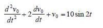
Design an analog computer to simulateWhere v0(0) = 2 and v'0(0) = 0.
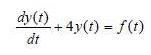
Design an analog computer circuit to solve the following ordinary differential equation.Where y(0) = 1 V.
A 4-mF capacitor has the terminal voltageIf the capacitor has initial current of 2A, find:(a) The constants A and B,(b) The energy stored in the capacitor at t = 0,(c) The capacitor current for t > 0.
Figure 6.93 presents an analog computer designed to solve a differential equation. Assuming f(t) is known, set up the equation for f(t).
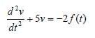
Design an analog computer to simulate the following equation:
Design an an op amp circuit such that:Where vs and v0 are the input voltage and output voltage respectively.
Your laboratory has available a large number of 10-μF capacitors rated at 300 V. To design a capacitor bank of 40-μF rated at 600 V, how many 10-μF capacitors are needed and how would you connect them?
An 8-mH inductor is used in a fusion power experiment. If the current through the inductor is i(t) = 5sin2 πt mA, t > 0, find the power being delivered to the inductor and the energy stored in it at t=0.5s.
A square-wave generator produces the voltage waveform shown in Fig. 6.94(a). What kind of a circuit component is needed to convert the voltage waveform to the triangular current waveform shown in Fig. 6.94(b)? Calculate the value of the component, assuming that it is initially uncharged.
An electric motor can be modeled as a series combination of a 12-Ω resistor and 200-mH inductor. If a current i(t) = 2te-10tA flows through the series combination, find the voltage across the combination.
The current through a 0.5-F capacitor is 6(1-e-t)A. Determine the voltage and power at t=2 s. Assume v(0) = 0.
In the circuit shown in Fig. 7.81v(t) = 56eˆ’200tV, t > 0i(t) = 8eˆ’200tmA, t > 0(a) Find the values of R and C.(b) Calculate the time constant Ï„.(c) Determine the time required for the voltage to decay half its initial value att = 0.
For the circuit in Fig. 7.90, find v0 (t) for t > 0. Determine the time necessary for the capacitor voltage to decay to one-third of its value at t = 0.
For the circuit in Fig. 7.91, find i0 for t > 0.
The switch in the circuit of Fig. 7.92 has been closed for a long time. At t = 0 the switch is opened. Calculate i(t) for t > 0.
Showing 7400 - 7500
of 8940
First
68
69
70
71
72
73
74
75
76
77
78
79
80
81
82
Last
Step by Step Answers
.png)
-2.png)
.png)
.png)
.png)
.png)
.png)
.png)
.png)
.png)
.png)
.png)
.png)
-1.png)
-2.png)
-3.png)
.png)
.png)
.png)
.png)
.png)
.png)
-1.png)
-2.png)
-2.png)
-3.png)
.png)
-1.png)
-2.png)
.png)
.png)
.png)
.png)
.png)
.png)
.png)
.png)
.png)
.png)
.png)
.png)
.png)
.png)
.png)
.png)
-1.png)
-2.png)
.png)
.png)
.png)
-3.png)
.png)
.png)
.png)
.png)
-1.png)
-2.png)
.png)
.png)
.png)
.png)
.png)
.png)
.png)
.png)
.png)
.png)
.png)
.png)
.png)
.png)

