New Semester
Started
Get
50% OFF
Study Help!
--h --m --s
Claim Now
Question Answers
Textbooks
Find textbooks, questions and answers
Oops, something went wrong!
Change your search query and then try again
S
Books
FREE
Study Help
Expert Questions
Accounting
General Management
Mathematics
Finance
Organizational Behaviour
Law
Physics
Operating System
Management Leadership
Sociology
Programming
Marketing
Database
Computer Network
Economics
Textbooks Solutions
Accounting
Managerial Accounting
Management Leadership
Cost Accounting
Statistics
Business Law
Corporate Finance
Finance
Economics
Auditing
Tutors
Online Tutors
Find a Tutor
Hire a Tutor
Become a Tutor
AI Tutor
AI Study Planner
NEW
Sell Books
Search
Search
Sign In
Register
study help
physics
electricity and magnetism
Fundamentals Of Electric Circuits 3rd Edition Matthew Sadiku, Charles Alexander - Solutions
In the op amp circuit of Fig. 10.118, find the closed-loop gain and phase shift of the output Voltage with respect to the input Voltage if Ci = C2 = nF, R1 = R2 = kΩ, 20 3 R3 = 20 kΩ, R4 = 40 kΩ and ω = 2000 rad/s.
Determine Vo and I o in the op amp circuit of Fig. 10.119.
Compute the closed-loop gain Vo /Vs for the op amp circuit of Fig. 10.120.
Determine vo (t) in the op amp circuit in Fig. 10.121 below.
For the op amp circuit in Fig. 10.122, obtain vo (t).
Use nodal analysis to find current io in the circuit of Fig. 10.57. Let is = 6cos(200t +15°) s A.
Obtain vo (t) for the op amp circuit in Fig. 10.123 if vs = 4cos(1000t ˆ’ 60°) V.
Use PSpice to determine Vo in the circuit of Fig. 10.124. Assume ω = 1 rad/s.
Solve Prob. 10.19 using PSpice.In Problem 10.19
Use PSpice to find vo (t) in the circuit of Fig. 10.125. Let is = 2 cos (103t) A.
Obtain Vo in the circuit of Fig. 10.126 using PSpice.
Use PSpice to find Vo in the circuit of Fig. 10.127.
Use PSpice to find V1, V2, and V3 in the network of Fig. 10.128.
Determine V1, V2, and V3 in the circuit of Fig. 10.129 using PSpice.
Use PSpice to find vo and io in the circuit of Fig. 10.130 below.
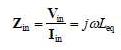
The op amp circuit in Fig. 10.131 is called an inductance simulator. Show that the input impedance is given byWhere
Use nodal analysis to find vo in the circuit of Fig. 10.58.
Figure 10.132 shows a Wien-bridge network. Show that the frequency at which the phase shift between the input and output signals is zero is f = 1 / 2 π RC, and that the necessary gain is Av = Vo / Vi = 3 at that frequency.
Consider the oscillator in Fig. 10.133.(a) Determine the oscillation frequency.(b) Obtain the minimum value of R for which oscillation takes place.
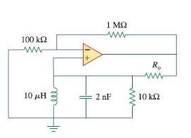
The oscillator circuit in Fig. 10.134 uses an ideal op amp.(a) Calculate the minimum value of Ro that will cause oscillation to occur.(b) Find the frequency of oscillation.
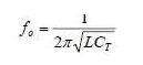
Figure 10.135 shows a Colpitts oscillator. Show that the oscillation frequency isWhere CT = C1C2 / (C1 + C2). Assume Ri >> XC2
Design a Colpitts oscillator that will operate at 50 kHz.
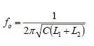
Figure 10.136 shows a Hartley oscillator. Show that the frequency of oscillation is
Refer to the oscillator in Fig. 10.137.(a) Show that(b) Determine the oscillation frequency fo.(c) Obtain the relationship between R1 and R2 in order for oscillation to occur.
Determine i in the circuit of Fig. 10.50.
Use nodal analysis to find vo in the circuit of Fig. 10.59. Let ω = 2 krad/s.
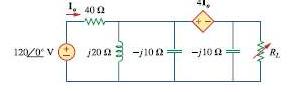
Apply nodal analysis to the circuit in Fig. 10.60 and determine Io.
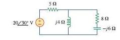
By nodal analysis, find io in the circuit of Fig. 10.61.
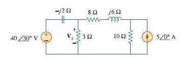
Determine Vx in the circuit of Fig. 10.62 using any method of your choice.
Calculate the voltage at nodes 1 and 2 in the circuit of Fig. 10.63 using nodal analysis.
Solve for the current I in the circuit of Fig. 10.64 using nodal analysis.
Use nodal analysis to find Vx in the circuit shown in Fig. 10.65.
By nodal analysis, obtain current Io in the circuit of Fig. 10.66.
Use nodal analysis to obtain Vo in the circuit of Fig. 10.67 below.
Obtain Vo in Fig. 10.68 using nodal analysis.
Solve for Vo in Fig. 10.51, using nodal analysis.
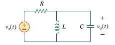
Refer to Fig. 10.69. If vs(t) = Vm = sin ωt and vo(t) = A (ωt +φ ) derive the expressions for A and φ
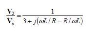
For each of the circuits in Fig. 10.70, find Vo / Vi for ω = 0,ω †’ˆž, and ω2 = 1/ LC .
For the circuit in Fig. 10.71, determine Vo / Vs.
Using nodal analysis obtain V in the circuit of Fig. 10.72.
Use mesh analysis to find Vo in the circuit of Prob. 10.2.
Solve for io in Fig. 10.73 using mesh analysis.
Use mesh analysis to find current io in the circuit of Fig. 10.74.
Using mesh analysis, find I1 and I2 in the circuit of Fig. 10.75.
In the circuit of Fig. 10.76, determine the mesh currents i1 and i2. Let v1 = 10cos 4t 1 = V and v2 = 20cos(4 ˆ’ 30°) V.
By using mesh analysis, find I1 and I2 in the circuit depicted in Fig 10.77
Determine vo in the circuit of Fig. 10.52.
Use mesh analysis to find vo in the circuit of Fig. 10.78. Let Vs1 = 120cos(100 + 90°) V, vs2 = 80 cos 100t V.
Use mesh analysis to determine current I o in the circuit of Fig. 10.79 below.
Determine Vo and Io in the circuit of Fig. 10.80 using mesh analysis.
Compute I in Prob. 10.15 using mesh analysisIn Problem 10.15
Use mesh analysis to find Io in Fig. 10.28 (for Example 10.10).
Calculate Io in Fig. 10.30 (for Practice Prob. 10.10) using mesh analysis.
Compute Vo in the circuit of Fig. 10.81 using mesh analysis.
Use mesh analysis to find currents I1, I2, and I 3 in the circuit of Fig. 10.82.
Using mesh analysis, obtain I o in the circuit shown in Fig. 10.83.
If v(t) = 160 cos 50t V and i(t) = -20 sin(50t - 30°) A, calculate the instantaneous power and the average power.
In the op amp circuit in Fig. 11.42, find the total average power absorbed by the resistors.
For the network in Fig. 11.43, assume that the port impedance isFind the average power consumed by the network when R = 10 kΩ, C = 200 nF, and i = 2 sin(377t + 22º) mA.
For the circuit shown in Fig. 11.44, determine the load impedance Z for maximum power transfer (to Z). Calculate the maximum power absorbed by the load.
The Thevenin impedance of a source is ZTh = 120 + j60 Ω, while the peak Thevenin voltage is VTh = 110 + j0 V . Determine the maximum available average power from the source.
It is desired to transfer maximum power to the load Z in the circuit of Fig. 11.45. Find Z and the maximum power. Let is = 5cos 40t A.
In the circuit of Fig. 11.46, find the value of ZL that will absorb the maximum power and the value of the maximum power.
For the circuit of Fig. 11.47, find the maximum power delivered to the load ZL.
Calculate the value of ZL in the circuit of Fig. 11.48 in order for ZL to receive maximum average power. What is the maximum average power received by ZL?
Find the value of ZL in the circuit of Fig. 11.49 for maximum power transfer.
The variable resistor R in the circuit of Fig. 11.50 is adjusted until it absorbs the maximum average power. Find R and the maximum average power absorbed.
Given the circuit in Fig. 11.35, find the average power supplied or absorbed by each element.
The load resistance RL in Fig. 11.51 is adjusted until it absorbs the maximum average power. Calculate the value of RL and the maximum average power.
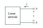
Assuming that the load impedance is to be purely resistive, what load should be connected to terminals a-b of the circuits in Fig. 11.52 so that the maximum power is transferred to the load?
Find the rms value of the offset sine wave shown in Fig. 11.53.
Determine the rms value of the waveform in Fig. 11.55.
Find the rms value of the signal shown in Fig. 11.56.
Find the effective value of the voltage waveform in Fig. 11.57.
Calculate the rms value of the current waveform of Fig. 11.58.
Find the rms value of the voltage waveform of Fig. 11.59 as well as the average power absorbed by a 2- Ω resistor when the voltage is applied across the resistor.
Calculate the effective value of the current waveform in Fig. 11.60 and the average power delivered to a 12- Ω resistor when the current runs through the resistor.
A load consists of a 60- Ω resistor in parallel with a 90μ F capacitor. If the load is connected to a voltage source s v (t) = 40 cos 2000t, find the average power delivered to the load.
Compute the rms value of the waveform depicted in Fig. 11.61.
Find the rms value of the signal shown in Fig. 11.62.
Obtain the rms value of the current waveform shown in Fig. 11.63.
Determine the rms value for the waveform in Fig. 11.64.
Find the effective value of f(t) defined in Fig. 11.65.
One cycle of a periodic voltage waveform is depicted in Fig. 11.66. Find the effective value of the voltage. Note that the cycle starts at t = 0 and ends at t = 6 s.
Calculate the rms value for each of the following functions: (a) i(t) = 10 A (b) v(t) = 4 + 3 cos 5t V (c) i(t) = 8 - 6 sin 2t A (d) v(t) = 5 sint + 4 cos t V
Calculate the rms value of the sum of these three currents: i1 = 8, i2 = 4 sin(t + 10º), i3 = 6 cos(2t + 30º) A
For the power system in Fig. 11.67, find:(a) The average power(b) The reactive power(c) The power factor. Note that 220 V is an rms value.
An ac motor with impedance ZL = 4.2 + j3.6 Ω is supplied by a 220-V, 60-Hz source. (a) Find pf, P, and Q. (b) Determine the capacitor required to be connected in parallel with the motor so that the power factor is corrected to unity.
Find the average power dissipated by the resistances in the circuit of Fig. 11.36. Additionally, verify the conservation of power.
A load consisting of induction motors is drawing 80 kW from a 220-V, 60-Hz power line at a pf of 0.72 lagging. Find the capacitance of a capacitor required to raise the pf to 0.92.
Obtain the power factor for each of the circuits in Fig. 11.68. Specify each power factor as leading or lagging.
A 110-V rms, 60-Hz source is applied to a load impedance Z. The apparent power entering the load is 120 VA at a power factor of 0.707 lagging. (a) Calculate the complex power. (b) Find the rms current supplied to the load. (c) Determine Z. (d) Assuming that Z = R + jω L, find the values of R and L.
The voltage applied to a 10- Ω resistor is v(t) = 5 + 3cos(t +10°) + cos(2t + 30°) V (a) Calculate the rms value of the voltage. (b) Determine the average power dissipated in the resistor.
Find the complex power delivered by vs to the network in Fig. 11.69.Let vs = 100 cos 2000t V.
The voltage across a load and the current through it are given by v(t) = 20 + 60 cos 100t V i(t) = 1 - 0.5 sin 100t A Find: (a) The rms values of the voltage and of the current (b) The average power dissipated in the load
For the following voltage and current phasors, calculate the complex power, apparent power, real power, and reactive power. Specify whether the pf is leading or lagging. (a) V = 220∠30° V rms, I = 0.5∠60° A rms (b) V = 250 ∠ - 10° V rms, I = 6.2 ∠ - 25° A rms (c) V = 80∠0° V rms, I =
For each of the following cases, find the complex power, the average power, and the reactive power: (a) v(t) = 112 cos(ω t + 10º) V, i(t) = 4 cos(ω t - 50º) A (b) v(t) = 160 cos 377t V, i(t) = 4 cos(377t + 45º) A (c) V = 80∠60° V rms, Z = 50∠30° Ω (d) I = 10∠60° A rms, Z = 100∠45°
Determine the complex power for the following cases: (a) P = 269 W, Q = 150 VAR (capacitive) (b) Q = 2000 VAR, pf = 0.9 (leading) (c) S = 600 VA, Q = 450 VAR (inductive) (d) Vrms = 220 V, P = 1 kW, |Z| = 40 Ω (inductive)
Find the complex power for the following cases: (a) P = 4 kW, pf = 0.86 (lagging) (b) S = 2 kVA, P = 1.6 kW (capacitive) (c) Vrms = 208 ∠ 20° V, Irms = 6.5 ∠ - 50° A (d) Vrms = 120 ∠ 30° V, = 40 + 60 Ω
Assuming that s v = 8 cos(2t - 40º) V in the circuit of Fig. 11.37, find the average power delivered to each of the passive elements.
Showing 7800 - 7900
of 8940
First
72
73
74
75
76
77
78
79
80
81
82
83
84
85
86
Last
Step by Step Answers
.png)
.png)
.png)
.png)
.png)
.png)
.png)
.png)
.png)
.png)
.png)
.png)
.png)
.png)
.png)
-2.png)
.png)
.png)
.png)
-2.png)
-2.png)
-2.png)
.png)
.png)
.png)
.png)
.png)
.png)
.png)
.png)
.png)
.png)
.png)
.png)
.png)
.png)
.png)
.png)
.png)
.png)
.png)
.png)
.png)
.png)
.png)
.png)
.png)
.png)
.png)
.png)
.png)
.png)
.png)
.png)
.png)
.png)
.png)
.png)
.png)
.png)
.png)
.png)
.png)
.png)
.png)
.png)
.png)
.png)
.png)
.png)
.png)
.png)
.png)
.png)
.png)
.png)
.png)
.png)

