New Semester
Started
Get
50% OFF
Study Help!
--h --m --s
Claim Now
Question Answers
Textbooks
Find textbooks, questions and answers
Oops, something went wrong!
Change your search query and then try again
S
Books
FREE
Study Help
Expert Questions
Accounting
General Management
Mathematics
Finance
Organizational Behaviour
Law
Physics
Operating System
Management Leadership
Sociology
Programming
Marketing
Database
Computer Network
Economics
Textbooks Solutions
Accounting
Managerial Accounting
Management Leadership
Cost Accounting
Statistics
Business Law
Corporate Finance
Finance
Economics
Auditing
Tutors
Online Tutors
Find a Tutor
Hire a Tutor
Become a Tutor
AI Tutor
AI Study Planner
NEW
Sell Books
Search
Search
Sign In
Register
study help
physics
electricity and magnetism
Fundamentals Of Electric Circuits 3rd Edition Matthew Sadiku, Charles Alexander - Solutions
A three-phase supply, with the line voltage 240 V rms positively phased, has an unbalanced delta-connected load as shown in Fig. 12.62. Find the phase currents and the total complex power.
Refer to the unbalanced circuit of Fig. 12.63. Calculate:(a) The line currents(b) The real power absorbed by the load(c) The total complex power supplied by the source
Determine the line currents for the three-phase circuit of Fig. 12.64. Let Va = 110ˆ 0°, Vb = 110ˆ ˆ’120°, Vc = 110ˆ 120° V.
The source in Fig. 12.65 is balanced and exhibits a positive phase sequence. If f = 60 Hz, use PSpice to find VAN, VBN, and VCN.
For the Y-Y circuit of Fig. 12.41, find the line currents, the line voltages, and the load voltages.
Use PSpice to determine Io in the single-phase, three-wire circuit of Fig. 12.66. Let Z1 = 15 - j10 Ω, Z2 = 30 + j20 Ω, and Z3 = 12 + j5 Ω.
Given the circuit in Fig. 12.67, use PSpice to determine currents IaA and voltage VBN.
The circuit in Fig. 12.68 operates at 60 Hz. Use PSpice to find the source current Iab and the line current IbB.
Use PSpice to find currents IaA and IAC in the unbalanced three-phase system shown in Fig. 12.69. LetZI = 2 + j, Z1 = 40 + j20 Ω,Z2 = 50 - j30Ω, Z3 = 25 Ω
For the circuit in Fig. 12.58, use PSpice to find the line currents and the phase currents.
A balanced three-phase circuit is shown in Fig. 12.70 on the next page. Use PSpice to find the line currents IaA, IbB, and IcC.
A three-phase, four-wire system operating with a 208-V line voltage is shown in Fig. 12.71. The source voltages are balanced. The power absorbed by the resistive wyeconnected load is measured by the three-wattmeter method. Calculate:(a) The voltage to neutral(b) The currents I1, I2, I3, and In(c)
aAs shown in Fig. 12.72, a three-phase four-wire line with a phase voltage of 120 V rms and positive phase sequence supplies a balanced motor load at 260 kVA at 0.85 pf lagging. The motor load is connected to the three main lines marked a, b, and c. In addition, incandescent lamps (unity pf) are
Meter readings for a three-phase wye-connected alternator supplying power to a motor indicate that the line voltages are 330 V, the line currents are 8.4 A, and the total line power is 4.5 kW. Find: (a) The load in VA (b) The load pf (c) The phase current (d) The phase voltage
A certain store contains three balanced three-phase loads. The three loads are: Load 1: 16 kVA at 0.85 pf lagging Load 2: 12 kVA at 0.6 pf lagging Load 3: 8 kW at unity pf The line voltage at the load is 208 V rms at 60 Hz, and the line impedance is 0.4 + j0.8 Ω . Determine the line current and
Obtain the line currents in the three-phase circuit of Fig. 12.42 on the next page.
The two-wattmeter method gives P1 = 1200 W and P2 = -400 W for a three-phase motor running on a 240-V line. Assume that the motor load is wye-connected and that it draws a line current of 6 A. Calculate the pf of the motor and its phase impedance.
In Fig. 12.73, two wattmeters are properly connected to the unbalanced load supplied by a balanced source such that Vab = 208ˆ 0° V with positive phase sequence.(a) Determine the reading of each wattmeter.(b) Calculate the total apparent power absorbed by the load.
If wattmeters W1 and W2 are properly connected respectively between lines a and b and lines b and c to measure the power absorbed by the delta-connected load in Fig. 12.44, predict their readings.
For the circuit displayed in Fig. 12.74, find the wattmeter readings.
Predict the wattmeter readings for the circuit in Fig. 12.75.
A man has a body resistance of 600 Ω. How much current flows through his ungrounded body: (a) When he touches the terminals of a 12-V autobattery? (b) When he sticks his finger into a 120-V light socket?
Show that the I2R losses will be higher for a 120-V appliance than for a 240-V appliance if both have the same power rating.
A three-phase generator supplied 3.6 kVA at a power factor of 0.85 lagging. If 2500 W are delivered to the load and line losses are 80 W per phase, what are the losses in the generator?
A three-phase 440-V, 51-kW, 60-kVA inductive load operates at 60 Hz and is wyeconnected. It is desired to correct the power factor to 0.95 lagging. What value of capacitor should be placed in parallel with each load impedance?
A balanced three-phase generator has an abc phase sequence with phase voltage Van = 255∠0° V. The generator feeds an induction motor which may be represented by a balanced Y-connected load with an impedance of 12 + j5 Ω per phase. Find the line currents and the load voltages. Assume a line
In a balanced three-phase Y-Y system, the source is an abc sequence of voltages and Van = 100 ∠20° V rms. The line impedance per phase is 0.6 + j1.2 Ω, while the per-phase impedance of the load is 10 + j14 Ω. Calculate the line currents and the load voltages.
A balanced three-phase source furnishes power to the following three loads: Load 1: 6 kVA at 0.83 pf lagging Load 2: unknown Load 3: 8 kW at 0.7071 pf leading If the line current is 84.6 A rms, the line voltage at the load is 208 V rms, and the combined load has a 0.8 pf lagging, determine the
A professional center is supplied by a balanced three-phase source. The center has four balanced three-phase loads as follows: Load 1: 150 kVA at 0.8 pf leading Load 2: 100 kW at unity pf Load 3: 200 kVA at 0.6 pf lagging Load 4: 80 kW and 95 kVAR (inductive) If the line impedance is 0.02 + j0.05
A balanced three-phase system has a distribution wire with impedance 2 + j6 Ω per phase. The system supplies two three-phase loads that are connected in parallel. The first is a balanced wye-connected load that absorbs 400 kVA at a power factor of 0.8 lagging. The second load is a balanced
A commercially available three-phase inductive motor operates at a full load of 120 hp (1 hp = 746 W) at 95 percent efficiency at a lagging power factor of 0.707. The motor is connected in parallel to a 80-kW balanced three-phase heater at unity power factor. If the magnitude of the line voltage is
Figure 12.76 displays a three-phase delta-connected motor load which is connected to a line voltage of 440 V and draws 4 kVA at a power factor of 72 percent lagging. In addition, a single 1.8 kVAR capacitor is connected between lines a and b, while a 800-W lighting load is connected between line c
Design a three-phase heater with suitable symmetric loads using wye-connected pure resistance. Assume that the heater is supplied by a 240-V line voltage and is to give 27 kW of heat.
For the single-phase three-wire system in Fig. 12.77, find currents IaA, IbB, and InN.
Consider the single-phase three-wire system shown in Fig. 12.78. Find the current in the neutral wire and the complex power supplied by each source. Take Vs as a 115ˆ 0° -V, 60-Hz source.
A balanced Y-Y four-wire system has phase voltages Van = 120 ∠0° Vbn = 120 ∠ - 120° Vcn = 120 ∠120° V The load impedance per phase is 19 + j13 Ω, and the line impedance per phase is 1 + j2 Ω . Solve for the line currents and neutral current.
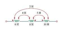
For the three coupled coils in Fig. 13.72, calculate the total inductance.
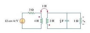
Find vo in the circuit of Fig. 13.79.
Use mesh analysis to find ix in Fig. 13.80,Where is = 4 cos(600t) A and vs = 110 cos(600t + 30º)
Determine the equivalent Leq in the circuit of Fig. 13.81.
For the circuit in Fig. 13.82, determine the impedance seen by the source.
Obtain the Thevenin equivalent circuit for the circuit in Fig. 13.83 at terminals a-b.
Find the Norton equivalent for the circuit IN Fig. 13.84 at terminals a-b.
Obtain the Norton equivalent at terminals a-b of the circuit in Fig. 13.85.
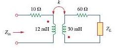
In the circuit of Fig. 13.86, ZL is a 15-mH inductor having an impedance of j40 Ω. Determine Zin when k = 0.6.
Find the Thevenin equivalent to the left of the load Z in the circuit of Fig. 13.87.
Determine an equivalent T-section that can be used to replace the transformer in Fig. 13.88.
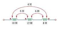
Determine the inductance of the three series-connected inductors of Fig. 13.73.
Determine currents I1, I2, and I3 in the circuit of Fig. 13.89. Find the energy stored in the coupled coils at t = 2 ms. Take ω = 1,000 rad/s.
Find I1 and I2 in the circuit of Fig. 13.90. Calculate the power absorbed by the 4- Ω resistor.
Find current Io in the circuit of Fig. 13.91.
If M = 0.2 H and vs = 12 cos 10t V in the circuit of Fig. 13.92, find I1 and I2 Calculate the energy stored in the coupled coils at t = 15 ms.
In the circuit of Fig. 13.93,(a) Find the coupling coefficient,(b) Calculate vo,(c) Determine the energy stored in the coupled inductors at t = 2 s.
For the network in Fig. 13.94, find Zab and Io.
Find Io in the circuit of Fig. 13.95. Switch the dot on the winding on the right and calculate Io again.
Find the average power delivered to the 50- Ω resistor in the circuit of Fig. 13.96.
In the circuit of Fig. 13.97, find the value of X that will give maximum power transfer to the 20- Ω load.
In the circuit of Fig. 13.98, find the value of the coupling coefficient k that will make the 10- Ω resistor dissipate 320 W. For this value of k, find the energy stored in the coupled coils at t = 1.5 s.
Two coils connected in series-aiding fashion have a total inductance of 250 mH. When connected in a series-opposing configuration, the coils have a total inductance of 150 mH. If the inductance of one coil (L1) is three times the other, find L1, L2, and M. What is the coupling coefficient?
Find the input impedance of the circuit in Fig. 13.99 using the concept of reflected impedance.Obtain the input impedance by replacing the linear transformer by its T equivalent.
For the circuit in Fig. 13.100, find:(a) The T-equivalent circuit,(b) The Î -equivalent circuit.
Two linear transformers are cascaded as shown in Fig. 13.101. Show that
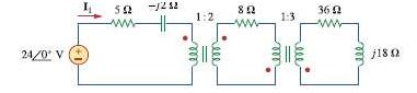
Determine the input impedance of the air-core transformer circuit of Fig. 13.102.
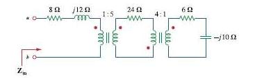
Find the input impedance of the circuit in Fig. 13.103.
Find currents I1, I2, and I3 in the circuit of Fig. 13.104.An asterisk indicates a challenging problem.
As done in Fig. 13.32, obtain the relationships between terminal voltages and currents for each of the ideal transformers in Fig. 13.105.
A 480/2,400-V rms step-up ideal transformer delivers 50 kW to a resistive load. Calculate: (a) The turns ratio (b) The primary current (c) The secondary current
A 4-kVA, 2,300/230-V rms transformer has an equivalent impedance of 2∠10° Ω on the primary side. If the transformer is connected to a load with 0.6 power factor leading, calculate the input impedance.
A 1,200/240-V rms transformer has impedance 60∠ − 30° Ω on the high-voltage side. If the transformer is connected to a 0.8∠10° -Ω load on the low-voltage side, determine the primary and secondary currents when the transformer is connected to 1200 V rms.
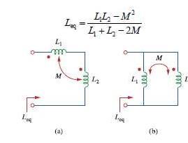
(a) For the coupled coils in Fig. 13.74(a), show thatLeq = L1 + L2 + 2M(b) For the coupled coils in Fig. 13.74(b), show that
The primary of an ideal transformer with a turns ratio of 5 is connected to a voltage source with Thevenin parameters vTh = 10 cos 2000t V and RTh = 100 Ω Determine the average power delivered to a 200- Ω load connected across the secondary winding.
Determine I1 and I2 in the circuit of Fig. 13.106.
For the circuit in Fig. 13.107, determine the power absorbed by the 2- Ω resistor. Assume the 80 V is an rms value.
Obtain v1 and v2 in the ideal transformer circuit of Fig. 13.108.
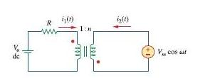
In the ideal transformer circuit of Fig. 13.109, find i1(t) and i2(t).An asterisk indicates a challenging problem.
For the circuit shown in Fig. 13.110, find the value of the average power absorbed by the 8- Ω resistor.
(a) Find I1 and I2 in the circuit of Fig. 13.111 below.(b) Switch the dot on one of the windings. Find I1 and I2 again.
Find v(t) for the circuit in Fig. 13.112.
Find Ix in the ideal transformer circuit of Fig. 13.113.
Find current ix in the ideal transformer circuit shown in Fig. 13.114.
Two coils are mutually coupled, with L1 = 25 mH, L2 = 60 mH, and k = 0.5. Calculate the maximum possible equivalent inductance if: (a) The two coils are connected in series (b) The coils are connected in parallel
Calculate the input impedance for the network in Fig. 13.115.
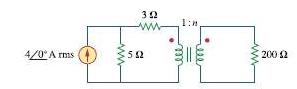
Use the concept of reflected impedance to find the input impedance and current I1 in Fig. 13.116.
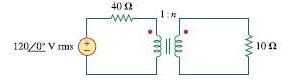
For the circuit in Fig. 13.117, determine the turns ratio n that will cause maximum average power transfer to the load. Calculate that maximum average power.
Refer to the network in Fig. 13.118.(a) Find n for maximum power supplied to the 200- Ω load.(b) Determine the power in the 200- Ω load if n = 10.
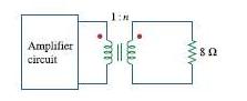
A transformer is used to match an amplifier with an 8- Ω load as shown in Fig. 13.119. The Thevenin equivalent of the amplifier is: VTh = 10 V, ZTh = 128 Ω.(a) Find the required turns ratio for maximum energy power transfer.(b) Determine the primary and secondary currents.(c) Calculate the
For the circuit in Fig. 13.120, calculate the equivalent resistance.
Find the power absorbed by the 10- Ω resistor in the ideal transformer circuit of Fig. 13.121.
For the ideal transformer circuit of Fig. 13.122 below, find:(a) I1 and I2,(b) v1, v2, and Vo,(c) The complex power supplied by the source.
Determine the average power absorbed by each resistor in the circuit of Fig. 13.123.
In the circuit of Fig. 13.124, let vs = 40 cos 1000t. Find the average power delivered to each resistor.
The coils in Fig. 13.75 have L1 = 40 mH, L2 = 5 mH, and coupling coefficient k = 0.6.Find i1 (t) and v2(t), given that v1(t) = 10 cos ω t and i2(t) = 2 sin ω t, ω = 2000 rad/s.
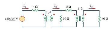
Refer to the circuit in Fig. 13.125 on the following page.(a) Find currents I1, I2, and I3.(b) Find the power dissipated in the 40- Ω resistor.
For the circuit in Fig. 13.126, find I1, I2, and Vo.
For the network in Fig. 13.127, find(a) The complex power supplied by the source,(b) The average power delivered to the 18- Ω resistor.
Find the mesh currents in the circuit of Fig. 13.128
For the circuit in Fig. 13.129, find the turns ratio so that the maximum power is delivered to the 30-k Ω resistor.
Calculate the average power dissipated by the 20- Ω resistor in Fig. 13.130.An asterisk indicates a challenging problem
An ideal autotransformer with a 1:4 step-up turns ratio has its secondary connected to a 120- Ω load and the primary to a 420-V source. Determine the primary current.
An autotransformer with a 40 percent tap is supplied by a 400-V, 60-Hz source and is used for step-down operation. A 5-kVA load operating at unity power factor is connected to the secondary terminals. Find: (a) The secondary voltage (b) The secondary current (c) The primary current
Showing 8000 - 8100
of 8940
First
74
75
76
77
78
79
80
81
82
83
84
85
86
87
88
Last
Step by Step Answers
.png)
.png)
.png)
.png)
.png)
.png)
.png)
.png)
.png)
.png)
.png)
.png)
.png)
.png)
.png)
.png)
.png)
.png)
.png)
.png)
.png)
.png)
.png)
.png)
.png)
.png)
.png)
.png)
.png)
.png)
.png)
.png)
.png)
.png)
.png)
.png)
.png)
.png)
.png)
-1.png)
-2.png)
.png)
.png)
.png)
.png)
.png)
.png)
.png)
.png)
.png)
.png)
.png)
.png)
.png)
.png)
.png)
.png)
.png)
.png)
.png)
.png)
.png)

