New Semester
Started
Get
50% OFF
Study Help!
--h --m --s
Claim Now
Question Answers
Textbooks
Find textbooks, questions and answers
Oops, something went wrong!
Change your search query and then try again
S
Books
FREE
Study Help
Expert Questions
Accounting
General Management
Mathematics
Finance
Organizational Behaviour
Law
Physics
Operating System
Management Leadership
Sociology
Programming
Marketing
Database
Computer Network
Economics
Textbooks Solutions
Accounting
Managerial Accounting
Management Leadership
Cost Accounting
Statistics
Business Law
Corporate Finance
Finance
Economics
Auditing
Tutors
Online Tutors
Find a Tutor
Hire a Tutor
Become a Tutor
AI Tutor
AI Study Planner
NEW
Sell Books
Search
Search
Sign In
Register
study help
physics
electricity and magnetism
Fundamentals Of Electric Circuits 3rd Edition Matthew Sadiku, Charles Alexander - Solutions
The switch in Fig. 16.58 moves from position 1 to position 2 at t = 0. Find v(t), for all t > 0.
For the RLC circuit shown in Fig. 16.59, find the complete response if v(0) = 2 V when the switch is closed.
For the op amp circuit in Fig. 16.60, find v0 (t) for t > 0. Take vs = 3eˆ’5t u(t) V.
Find I1 (s) and I2 (s) in the circuit of Fig. 16.61.
For the circuit in Fig. 16.62, find v 0 (t) for t > 0.
For the ideal transformer circuit in Fig. 16.63, determine i0 (t).
Find i(t) for t > 0 for the circuit in Fig. 16.37. Assume is = 4u(t) + 2δ (t)mA. (Hint: Can we use superposition to help solve this problem?)
The transfer function of a system is H(s) = s2/3s+ 1 Find the output when the system has an input of 4e−t / 3 u(t).
When the input to a system is a unit step function, the response is 10 cos 2tu(t). Obtain the transfer function of the system.
A circuit is known to have its transfer function as H(s) = s + 3/s2 + 4s + 5 Find its output when: (a) The input is a unit step function (b) The input is 6te−2t u(t).
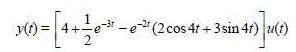
When a unit step is applied to a system at t = 0 its response isWhat is the transfer function of the system?
For the circuit in Fig. 16.64, find H(s) = V0 (s)/Vs (s). Assume zero initial conditions.
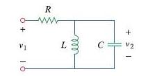
Obtain the transfer function H(s) = V0 /Vs for the circuit of Fig. 16.65.
For the circuit in Fig. 16.66, find:(a) I1 /Vs(b) I2 /Vx
Refer to the network in Fig. 16.67. Find the following transfer functions:(a) H1 (s) = V0 (s)/Vs (s)(b) H2 (s) = V0 (s)/Is (s)(c) H3 (s) = I0 (s)/Is (s)(d) H4 (s) = I0 (s)/Vs (s)
Calculate the gain H(s) = V0 /Vs in the op amp circuit of Fig. 16.68.
The capacitor in the circuit of Fig. 16.38 is initially uncharged. Find v0 (t) for t > 0.
Refer to the RL circuit in Fig. 16.69. Find:(a) The impulse response h(t) of the circuit.(b) The unit step response of the circuit.
A parallel RL circuit has R = 4Ω and L = 1 H. The input to the circuit is is (t) = 2e-t u(t)A. Find the inductor current iL (t) for all t > 0 and assume that iL (0) = -2 A.
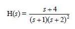
A circuit has a transfer functionFind the impulse response.
Develop the state equations for Prob. 16.1.
Develop the state equations for Prob. 16.2.
Develop the state equations for the circuit shown in Fig. 16.70.
Develop the state equations for the circuit shown in Fig. 16.71.
Develop the state equations for the circuit shown in Fig. 16.72.
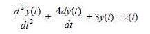
Develop the state equations for the following differential equation.
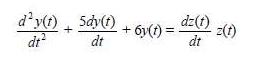
* Develop the state equations for the following differential equation.* An asterisk indicates a challenging problem.
If is (t) = eˆ’2t u(t) A in the circuit shown in Fig. 16.39, find the value of i 0 (t).
* Develop the state equations for the following differential equation.* An asterisk indicates a challenging problem.
* Given the following state equation, solve for y(t):* An asterisk indicates a challenging problem.
* Given the following state equation, solve for y1 (t).* An asterisk indicates a challenging problem.
Show that the parallel RLC circuit shown in Fig. 16.73 is stable.
A system is formed by cascading two systems as shown in Fig. 16.74. Given that the impulse response of the systems areh1 (t) = 3eˆ’t u(t), h2 (t) = eˆ’4t u(t)(a) Obtain the impulse response of the overall system.(b) Check if the overall system is stable.
Determine whether the op amp circuit in Fig. 16.75 is stable.
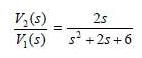
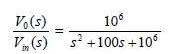
It is desired to realize the transfer functionusing the circuit in Fig. 16.76. Choose R = 1 kΩ and find L and C.
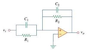
Design an op amp circuit, using Fig. 16.77, that will realize the following transfer function:Choose C1 = 10μF; determine R1, R2, and C2
Realize the transfer functionV0(s)/Vs(s) = s/s + 10using the circuit in Fig. 16.78. Let Y1 = sC1, Y2 = 1/R1, Y3 = sC2. Choose R1 = 1k Ω and determine C1 and C2.
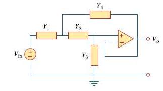
Synthesize the transfer functionusing the topology of Fig. 16.79. Let Y1 = 1/1 R, Y2 = 1/R2, Y3 = sC1, Y4 sC2. Choose R1 = 1k Ω and determine C1, C2, and R2.
Find v(t), t > 0 in the circuit of Fig. 16.40. Let v s= 20 V.
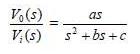
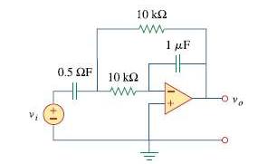
Obtain the transfer function of the op amp circuit in Fig. 16.80 in the form ofwhere a, b, and c are constants. Determine the constants.
A certain network has an input admittance Y(s). The admittance has a pole at s = -3, a zero at s = -1, and Y(∞) = 0.25 S. (a) Find Y(s). (b) An 8-V battery is connected to the network via a switch. If the switch is closed at t = 0, find the current i(t) through Y(s) using the Laplace transform.
A gyrator is a device for simulating an inductor in a network. A basic gyrator circuit is shown in Fig. 16.81. By finding Vi(s)/I0(s), show that the inductance produced by the gyrator is L = CR2.
Find v 0 (t), for all t > 0, in the circuit of Fig. 16.41.
If v0 (0) = -1V,obtain v0 (t) in the circuit of Fig. 16.42.
Find the input impedance Zin (s) of each of the circuits in Fig. 16.43.
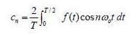
Evaluate each of the following functions and see if it is periodic. If periodic, find its period. (a) f (t) = cos π t + 2 cos 3 π t + 3 cos 5 π t (b) y(t) = sin t + 4 cos 2 π t (c) g(t) = sin 3t cos 4t (d) h(t) = cos2 t (e) z(t) = 4.2 sin(0.4 π t + 10º) + 0.8 sin(0.6 π t + 50º) (f) p(t) =
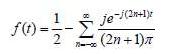
Find the exponential Fourier series for the waveform in Fig. 17.53.
Obtain the exponential Fourier series for the signal in Fig. 17.54.
* A voltage source has a periodic waveform defined over its period as v(t) = t(2π − t) V, 0 < t < 2π Find the Fourier series for this voltage. * An asterisk indicates a challenging problem.
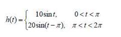
A periodic function is defined over its period asFind the Fourier series of h(t).
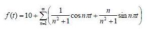
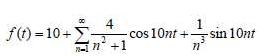
Find the quadrature (cosine and sine) form of the Fourier series
Express the Fourier series(a) In a cosine and angle form.(b) In a sine and angle form.
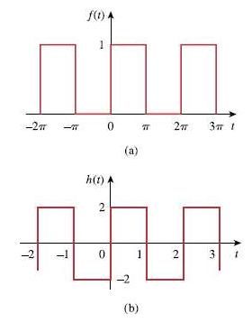
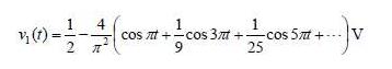
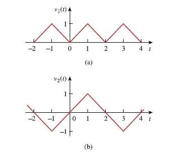
The waveform in Fig. 17.55(a) has the following Fourier series:Obtain the Fourier series of V2 (t) in Fig. 17.55(b).
Determine if these functions are even, odd, or neither. (a) 1 + t (b) t2 −1 (c) cos nπt sin nπt (d) sin2πt (e) e−t
Determine the fundamental frequency and specify the type of symmetry present in the functions in Fig. 17.56.
Obtain the Fourier series for the periodic waveform in Fig. 17.57.
Using MATLAB, synthesize the periodic waveform for which the Fourier trigonometric Fourier series is
Find the Fourier series for the signal in Fig. 17.58. Evaluate f(t) at t = 2 using the first three nonzero harmonics.
Determine the trigonometric Fourier series of the signal in Fig. 17.59.
Calculate the Fourier coefficients for the function in Fig. 17.60.
Find the Fourier series of the function shown in Fig. 17.61.
In the periodic function of Fig. 17.62,(a) Find the trigonometric Fourier series coefficients a2 and b2,(b) Calculate the magnitude and phase of the component of f(t) that has ωn = 10 rad/s,(c) Use the first four nonzero terms to estimate f (π / 2).(d) Show that
Determine the Fourier series representation of the function in Fig. 17.63.
Find the Fourier series representation of the signal shown in Fig. 17.64.
For the waveform shown in Fig. 17.65 below,(a) Specify the type of symmetry it has,(b) Calculate a3 and b3,(c) Find the rms value using the first five nonzero harmonics.
Obtain the trigonometric Fourier series for the voltage waveform shown in Fig. 17.66.
Determine the Fourier series expansion of the sawtooth function in Fig. 17.67.
Give the Fourier coefficients a0, an, and bn of the waveform in Fig. 17.47. Plot the amplitude and phase spectra.
(a) If f(t) is an even function, show that(b) If f(t) is an odd function, show that
Let an and bn be the Fourier series coefficients of f(t) and let ωo be its fundamental frequency. Suppose f(t) is time-scaled to give h(t) = f(α t). Express the a'n and b'n, and ω'o, of h(t) in terms of an, bn, and ωo of f(t).
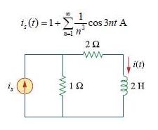
Find i(t) in the circuit of Fig. 17.68 given that
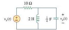
In the circuit shown in Fig. 17.69, the Fourier series expansion of vs(t) isFind vo(t).
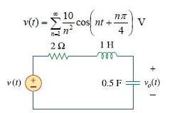
Obtain vo(t) in the network of Fig. 17.70 if
If vs in the circuit of Fig. 17.71 is the same as function f2(t) in Fig. 17.56(b), determine the dc component and the first three nonzero harmonics of vo(t).
Find the response io for the circuit in Fig. 17.72(a), where v(t) is shown in Fig. 17.72(b).
If the periodic current waveform in Fig. 17.73(a) is applied to the circuit in Fig. 17.73(b), find vo.
If the square wave shown in Fig. 17.74(a) is applied to the circuit in Fig. 17.74(b), find the Fourier series for vo(t).
If the periodic voltage in Fig. 17.75(a) is applied to the circuit in Fig. 17.75(b), find io(t).
Find the Fourier series expansion of the backward sawtooth waveform of Fig. 17.48. Obtain the amplitude and phase spectra.
The signal in Fig. 17.76(a) is applied to the circuit in Fig. 17.76(b). Find vo(t).
The full-wave rectified sinusoidal voltage in Fig. 17.77(a) is applied to the lowpass filter in Fig. 17.77(b). Obtain the output voltage vo(t) of the filter.
The square wave in Fig. 17.78(a) is applied to the circuit in Fig. 17.78(b). Find the Fourier series of vo(t).
The voltage across the terminals of a circuit is V(t) = 30 + 20 cos(60 πt + 45°) + 10 cos(60π - 45°) V If the current entering the terminal at higher potential is I(t) = 6 + 4 cos (60 πt - 45°) + 10 cos(60 πt - 45°) V find: (a) The rms value of the voltage, (b) The rms value of the
The voltage and current through an element are, respectively, V(t) = 30 cos(t + 25°) + 10 cos(2t + 35°) + 4 cos(3t - 10°) V I(t) = 2 cos t + cos (2t + 10°) A (a) Find the average power delivered to the element. (b) Plot the power spectrum.
A series RLC circuit has R = 10 Ω , L = 2 mH, and C = 40 μ F. Determine the effective current and average power absorbed when the applied voltage is V(t) 100 cos 1000 + 50 cos 2000t + 25 cos 3000t V
Use MATLAB to plot the following sinusoids for 0 < t < 5: (a) 5 cos 3t - 2 cos(3t-π /3) (b) 8 sin(π t + π /4) + 10 cos(π t-π /8)
The periodic current waveform in Fig. 17.79 is applied across a 2-k Ω resistor. Find the percentage of the total average power dissipation caused by the dc component.
For the circuit in Fig. 17.80,I(t) = 20 + 16 cos(10t + 45°)+ 12 cos(20t - 60°)mA(a) Find v(t), and(b) Calculate the average power dissipated in the resistor.
(a) For the periodic waveform in Prob. 17.5, find the rms value.(b) Use the first five harmonic terms of the Fourier series in Prob. 17.5 to determine the effective value of the signal.(c) Calculate the percentage error in the estimated rms value of z(t) if
Obtain the Fourier series expansion for the waveform shown in Fig. 17.49.
Obtain the exponential Fourier series for f(t) = t, -1 < t < 1, with f(t + 2n) = f(t) for all integer values of n.
Given the periodic function f(t) = t2, 0 < t < T Obtain the exponential Fourier series for the special case T = 2.
Calculate the complex Fourier series for f(t) = et, −π < t
Find the complex Fourier series for f (t) = e−t, 0 < t < 1, with f(t + n) = f(t) for all integer values of n.
Find the exponential Fourier series for the function in Fig. 17.81.
Obtain the exponential Fourier series expansion of the half-wave rectified sinusoidal current of Fig. 17.82.
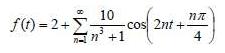
The Fourier series trigonometric representation of a periodic function isFind the exponential Fourier series representation of f(t).
The coefficients of the trigonometric Fourier series representation of a function are:If ωn = 50n, find the exponential Fourier series for the function.
Find the exponential Fourier series of a function that has the following trigonometric Fourier series coefficients:Take T = 2Ï€.
The complex Fourier series of the function in Fig. 17.83(a) isFind the complex Fourier series of the function h(t) in Fig. 17.83(b).
Showing 8300 - 8400
of 8940
First
76
77
78
79
80
81
82
83
84
85
86
87
88
89
90
Step by Step Answers
.png)
.png)
.png)
.png)
.png)
.png)
.png)
.png)
.png)
.png)
.png)
.png)
.png)
.png)
.png)
.png)
.png)
.png)
.png)
.png)
.png)
.png)
.png)
.png)
.png)
.png)
.png)
.png)
.png)
.png)
.png)
.png)
.png)
.png)
.png)
.png)
.png)
.png)
.png)
.png)
.png)
.png)
.png)
.png)
.png)
.png)
.png)
.png)
.png)
.png)
.png)
.png)
.png)
.png)
.png)
.png)