

Question: Repeat Problem 7.21 if the input signal is a current source of value i i applied at the base of Q 1 . (That is,
Data from Prob. 7.21:
A Darlington stage and a common-collector€“common-emitter cascade are shown schematically in Fig. 7.40, where RS = 100 kΩ and RL = 3 kΩ.
(a) Calculate the low-frequency small-signal voltage gain Ï…o/Ï…i for each circuit.
(b) Use the zero-value time-constant method to calculate the ˆ’3-dB frequency of the gain of each circuit. Data: β = 100, fT = 500 MHz at IC = 1 mA, Cμ = 0.4 pF,Cje = 2 pF, Ccs = 1 pF, rb = 0, ro = ˆž, IC1 = 10 µA, and IC2 = 1mA. (Values of Cμ, Ccs, and Cje are at the bias point.)
Fig. 7.40:
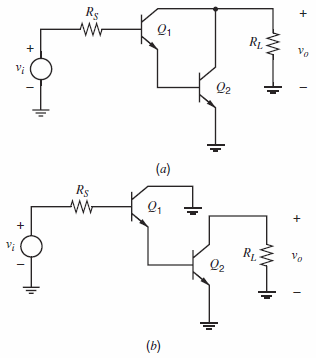
Rg RL Vo V Q2 (a) Rs R1 Q2 Vo (b)
Step by Step Solution
3.34 Rating (172 Votes )
There are 3 Steps involved in it
a In both cases R i r 1 1 g m1 r 2 520 K b Darlington R cso C cs1 C cs2 ... View full answer

Get step-by-step solutions from verified subject matter experts
Document Format (2 attachments)
1528_605d88e1b8697_686930.pdf
180 KBs PDF File
1528_605d88e1b8697_686930.docx
120 KBs Word File