

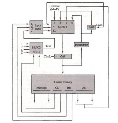
Question: Insert an exclusive-OR gate between MUX 2 and the input logic of Fig. 7-8. One input to the gate comes from the test output of
Insert an exclusive-OR gate between MUX 2 and the input logic of Fig. 7-8. One input to the gate comes from the test output of the multiplexer. The other input to the gate comes from a bit labeled P (for polarity) in the microinstruction from control memory. The output of the gate goes to the input T of the input logic. What does the polarity control P accomplish?
Fig. 7-8
1152 317 Input logic MUX2 Select External (MAP) Test Microops 3210 S MUX 1 So Clock>> CAR Control memory BR Incrementer AD SBR Load
Step by Step Solution
3.38 Rating (157 Votes )
There are 3 Steps involved in it
The introduction of an exclusiveOR XOR gate between MUX 2 and the input logic of the given system wi... View full answer

Get step-by-step solutions from verified subject matter experts