

Question: In the previous chapter, we used the root locus to design a proportional controller for the speed control of an HEV. We rearranged the block
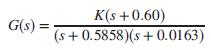
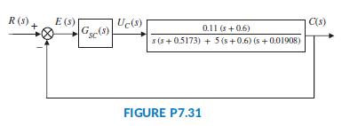
In the previous chapter, we used the root locus to design a proportional controller for the speed control of an HEV. We rearranged the block diagram to be a unity feedback system, as shown in the block diagram of Figure P7.31 (Preitl, 2007). The plant and compensator resulted in
and we found that K = 0.78 resulted in a critically damped system.
a. Use this design to itemize the performance specifications by filling in a table, similar to Table 9.5, under the column Uncompensated. Take advantage of the results from Chapter 8 or use MATLAB to find the entries. Plot c(t) for r(t) = 4 u(t) volts.
b. Now assume that the system specifications require zero steady-state error for step inputs, a steady-state error for ramp inputs 2%,a %OS 4.32%,and a settling time 4 sec. It should be evident that this is not accomplished with a proportional controller. Thus, start by designing a PI controller to meet the requirements. If necessary, add a PD mode to get a PID controller. Simulate your final design using MATLAB. Fill in the results of this design in the second column of your table with the heading Compensated.
c. Now note the following limitations of linear control system modeling:
1. No limit is set on system variables. For example, vehicle acceleration as well as motor and power amplifier current, torque or power do not have upper limits.
2. It is assumed that to improve the speed of response in Part b, we could place the PI controller’s zero on top of the pole closest to the origin. Realistically, such pole-zero cancellation is not always possible to maintain. If you do not expand your model beyond the described limitations if required for accuracy, unrealistic response characteristics, such as rise and settling times could result. Look at your design results including response curves. Are they realistic? If not, revise your Simulink model, which you developed for Problem 5.79, according to the following 4 steps:
i. Represent the motor armature as a first-order system with a unity steady-state gain and a time constant of 50 ms, which avoids the creation of internal algebraic closed-loops and should have negligible effect on system response;
ii. Add a saturation element at the output of the motor armature and set it to an upper limit of 250 A;
iii. Use the following PI settings. The PI settings of the speed controller are P = 61 and I = 0.795. The PI settings of the torque controller are P = 10 and I = 6;
iv. Run the modified model and comment on the graphs obtained for motor current, car acceleration, and speed.
K(s+0.60) (s+ 0.5858)(s + 0.0163) G(s) =
Step by Step Solution
3.50 Rating (153 Votes )
There are 3 Steps involved in it

Get step-by-step solutions from verified subject matter experts