

Question: The antenna positioning system described in Section 1.5 and Problem 1.5-1 is depicted in Fig. P4.3-11. In this problem we consider the yaw angle control
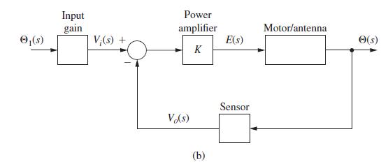
The antenna positioning system described in Section 1.5 and Problem 1.5-1 is depicted in Fig. P4.3-11. In this problem we consider the yaw angle control system, where θ(t) is the yaw angle.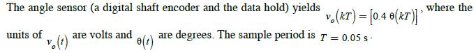
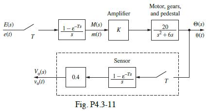
(a) Find the transfer function Θ(z)/E(z).
(b) The yaw angle is initially zero. The input voltage e(t) is set equal to 10 V at t = 0 , and is zero at each sample period thereafter. Find the steady-state value of the yaw angle.
(c) Note that in part (b), the coefficients in the partial-fraction expansion add to zero. Why does this occur?
(d) The input voltage e(t) is set to a constant value. Without solving mathematically, give a description of the system response.
(e) Suppose in part (d) that you are observing the antenna. Describe what you would see.
Problem 1.5-1
The antenna positioning system described in Section 1.5 is shown in Fig. P1.5–1. In this problem we consider the yaw angle control system, where w(t) is the yaw angle. Suppose that the gain of the power amplifier is 5 V/V, and that the gear ratio and the angle sensor (the shaft encoder and the data hold) are such that![]()
where the units of vo(t) are volts and of w(t) are degrees. Let e(t) be the input voltage to the motor; the transfer function of the motor pedestal is given as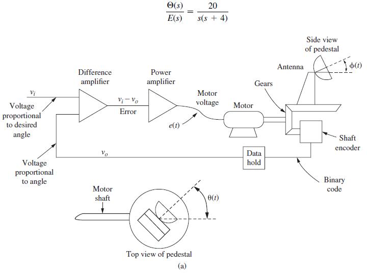
The angle sensor (a digital shaft encoder and the data hold) yields units of v. (t) are volts and e(t) v. (KT) = [0.4 0(KT)]* are degrees. The sample period is 7 = 0.05 s - where the
Step by Step Solution
3.47 Rating (160 Votes )
There are 3 Steps involved in it
21 a KGz K 20 Z 5 56 K b Ez 10 20K z0310740810740802222 36 z1z 6 002268z 002052 c0 0 C2 1... View full answer

Get step-by-step solutions from verified subject matter experts