

Question: A block diagram for a 16-bit 2s complement serial subtracter is given here. When St = 1, the registers are loaded and then subtraction occurs.
(a) Draw a state diagram for the control (two states).
(b) Write Verilog code for the system. Use two always blocks. The first always block should determine the next state and control signals; the second always block should update the registers on the rising edge of the clock.
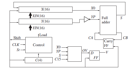
X(16) XIN(16) YP Full Y(16) adder YIN(16) Load Shift CA CB Carry FF CLK Control XO St ov YP FF C15 C(4)
Step by Step Solution
★★★★★
3.41 Rating (170 Votes )
There are 3 Steps involved in it
1 Expert Approved Answer
Step: 1 Unlock

a b module subtracterXIN YIN CLK St X Y V input 150 XIN YIN input CLK St outp... View full answer
Question Has Been Solved by an Expert!
Get step-by-step solutions from verified subject matter experts
Step: 2 Unlock
Step: 3 Unlock