

Question: Manually simulate the single- cycle computer in Figure 8-15 for the following sequence of instructions, assuming that each register initially contains contents equal to its
Manually simulate the single- cycle computer in Figure 8-15 for the following sequence of instructions, assuming that each register initially contains contents equal to its index (i.e., R0 contains 0, R1 contains 1, and so on):
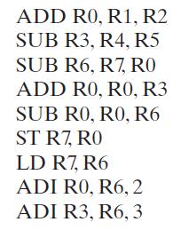
Figure 8-15
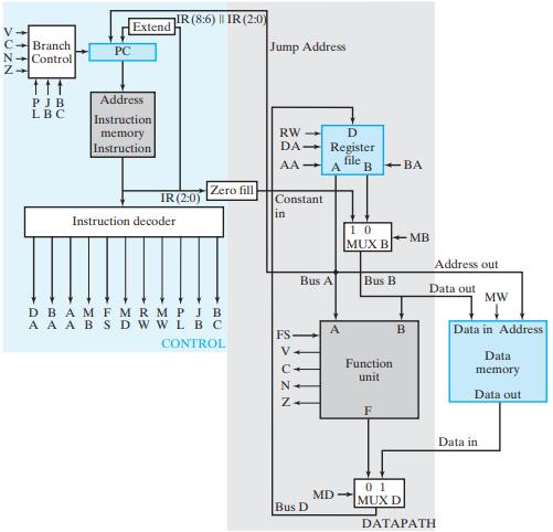
Give (a) the binary value of the instruction on the current line of the results and(b) the contents of any register changed by the instruction, or the location and contents of any memory location changed by the instruction on the next line of the results. The results are positioned in this fashion because the new values do not appear in a register or memory, due to the execution of an instruction, until after a positive clock edge has occurred.
ADD R0, R1, R2 SUB R3, R4, R5 SUB R6, R7, RO ADD RO, RO, R3 SUB RO, RO, R6 ST R7, R0 LD R7, R6 ADI R0, R6, 2 ADI R3, R6, 3
Step by Step Solution
3.41 Rating (151 Votes )
There are 3 Steps involved in it
Instruction ADD RO R1 R2 SUB R3 R4 R5 Code RegistersMemory changed 000 0101 ... View full answer

Get step-by-step solutions from verified subject matter experts