

Question: Using Figure 3-28 as a guide, write a structural VHDL description for the full-adder circuit in Figure 3-58. Compile and simulate your description. Apply all
Using Figure 3-28 as a guide, write a structural VHDL description for the full-adder circuit in Figure 3-58. Compile and simulate your description. Apply all eight input combinations to check the correction function of your description.
Figure 3-28
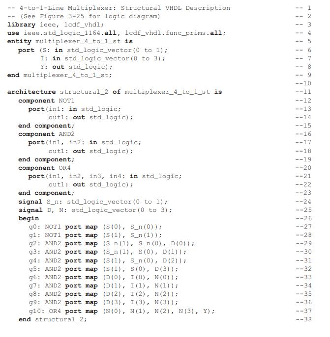
Figure 3-58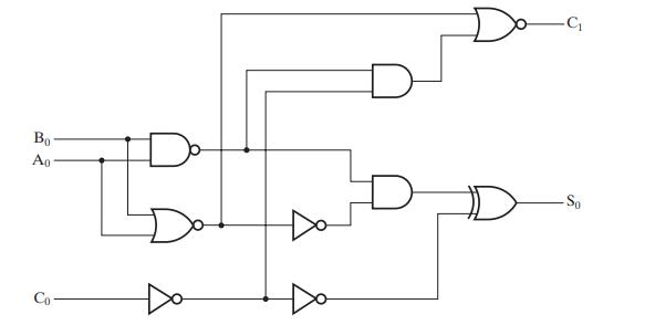
4-to-1-Line Multiplexer: Structural VHDL Description (See Figure 3-25 for logic diagram) library ieee, 1cdf_vhdl; use ieee.std_logic_1164.all, lcdf_vhdl. func_prims.all; entity multiplexer_4_to_1_st is port (S: in std_logic_vector (0 to 1); I: in std_logic vector (0 to 3); Y: out std_logic); end multiplexer_4_to_1_st; architecture structural_2 of multiplexer_4_to_1_st is component NOT1 port (inl: in std_logic; outl: out std_logic); end component; component AND2 port (inl, in2: in std_logic; outl: out std_logic); end component; component OR4 port (inl, in2, in3, in4: in std_logic; outl: out std_logic); end component; signal S_n: std_logic_vector (0 to 1); signal D, N: std_logic_vector (0 to 3); begin g0: NOT1 port map (S (0), S_n (0)); g1: NOT1 port map g2: AND2 port map g3: AND2 port map g4: AND2 port map g5: AND2 port map g6: AND2 port map g7: AND2 port map g8: AND2 port map (S(1), S_n (1)); (S_n (1), Sn (0), D (0) ) ; (S_n (1), S (0), D (1)); (S(1), S_n (0), D (2)); (S(1), S (0), D (3)); (D(0), I (0), N (0)); (D(1), I (1), N (1)); (D (2), I(2), N (2)); g9: AND2 port map (D(3), I(3), N (3)); g10: OR4 port map (N(0), N (1), N (2), N (3), Y); end structural_2; 1 GA WNH -- 2 -- 3 4 67 -- 7 8 -- 9 --10 --11 --12 --13 --14 --15 --16 --17 --18 --19 --20 --21 --22 --23 --24
Step by Step Solution
3.33 Rating (159 Votes )
There are 3 Steps involved in it
Based on the image of the VHDL code provided for a 4to1 line multiplexer and the schematic diagram of the full adder we can deduce how to write a stru... View full answer

Get step-by-step solutions from verified subject matter experts