

Question: 1)Design the 8-bit input register that can parallel load data to be transmitted as shown in the figure. 2) Design the 10-bit shift register (for
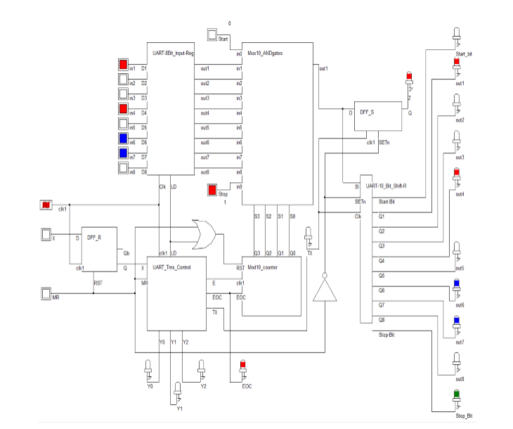
1)Design the 8-bit input register that can parallel load data to be transmitted as shown in the figure.
2) Design the 10-bit shift register (for storing the output of the multiplexer) that can shift right and parallel output data to the LEDs for testing purpose only as shown in the figure. 3) Design the 10-to-1 multiplexer that will be used to sandwich your 8-bits test data between 0 and 1.
4) Design the mod 10 counter as shown in the figure.
5) Design the Transmitter controlle
Step by Step Solution
There are 3 Steps involved in it
1 Expert Approved Answer
Step: 1 Unlock

Question Has Been Solved by an Expert!
Get step-by-step solutions from verified subject matter experts
Step: 2 Unlock
Step: 3 Unlock