

Question: 2. Given the following code: module clock_gate(input wire clk, enable, din, set,output reg dout); always @(negedge clk or posedge set) begin if (set) dout else
2. Given the following code:
module clock_gate(input wire clk, enable, din, set,output reg dout);
always @(negedge clk or posedge set) begin
if (set)
dout
else if (enable)
dout
end
endmodule
a. Synthesize to insert clock gating circuitry. (15pts)
b. Instantiate the original code and netlist in a testbench and test them in parallel to verify identical functionality. Compare the output of both models and increment an error counter if they differ. Turn in your testbench code, the netlist, and a waveform showing the I/O of the original code, I/O of the netlist, and an error counter. (20pts)
The testbench will look like:
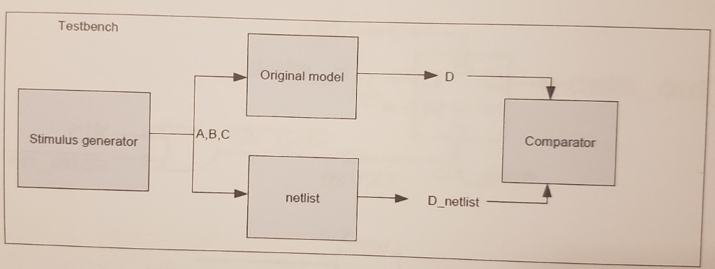
c. From the simulation in part b. what is the delay from a negative edge on input clk to a falling edge on output D_netlist? Show the delay in a simulation waveform. (10pts)
Testbench Original model A,B,C Comparator Stimulus generator netlist D_netlist Testbench Original model A,B,C Comparator Stimulus generator netlist D_netlist
Step by Step Solution
There are 3 Steps involved in it

Get step-by-step solutions from verified subject matter experts