

Question: 2. Ripple carry binary adder Implement a 4-bit ripple carry binary adder with inputs A3-0, B3-o and Cin and outputs S3-, and comes using the
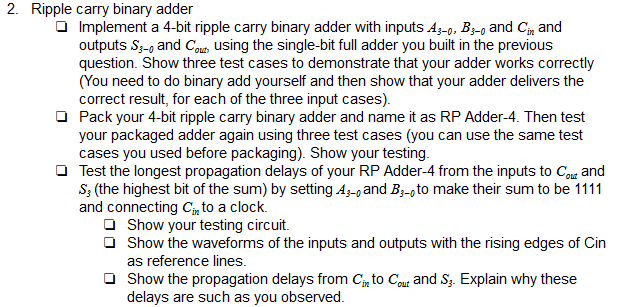
2. Ripple carry binary adder Implement a 4-bit ripple carry binary adder with inputs A3-0, B3-o and Cin and outputs S3-, and comes using the single-bit full adder you built in the previous question. Show three test cases to demonstrate that your adder works correctly (You need to do binary add yourself and then show that your adder delivers the correct result, for each of the three input cases). Pack your 4-bit ripple carry binary adder and name it as RP Adder-4. Then test your packaged adder again using three test cases (you can use the same test cases you used before packaging). Show your testing. Test the longest propagation delays of your RP Adder-4 from the inputs to cow and S; (the highest bit of the sum) by setting Az-, and B3-, to make their sum to be 1111 and connecting Cinto a clock. Show your testing circuit. Show the waveforms of the inputs and outputs with the rising edges of Cin as reference lines. Show the propagation delays from Cinto Cour and Sz. Explain why these delays are such as you observed. 2. Ripple carry binary adder Implement a 4-bit ripple carry binary adder with inputs A3-0, B3-o and Cin and outputs S3-, and comes using the single-bit full adder you built in the previous question. Show three test cases to demonstrate that your adder works correctly (You need to do binary add yourself and then show that your adder delivers the correct result, for each of the three input cases). Pack your 4-bit ripple carry binary adder and name it as RP Adder-4. Then test your packaged adder again using three test cases (you can use the same test cases you used before packaging). Show your testing. Test the longest propagation delays of your RP Adder-4 from the inputs to cow and S; (the highest bit of the sum) by setting Az-, and B3-, to make their sum to be 1111 and connecting Cinto a clock. Show your testing circuit. Show the waveforms of the inputs and outputs with the rising edges of Cin as reference lines. Show the propagation delays from Cinto Cour and Sz. Explain why these delays are such as you observed
Step by Step Solution
There are 3 Steps involved in it

Get step-by-step solutions from verified subject matter experts