

Question: 3 Implement the Full Subtractor circuit shown on slide 16. Show the Logisim version (picture) of the circuit and its corresponding Truth table (no .circ
3
Implement the Full Subtractor circuit shown on slide 16. Show the Logisim version (picture) of the circuit and its corresponding Truth table (no .circ files needed just picture and truth table).. Implement the Full Subtractor circuit shown on slide 16 in the Combinational Logic slide presentation. Show the Logisim version (picture) of the circuit and its corresponding Truth table (no .circ files needed just picture and truth table).
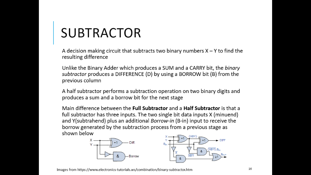
SUBTRACTOR A decision making circuit that subtracts two binary numbers X- Y to find the resulting difference Unlike the Binary Adder which produces a SUM and a CARRY bit, the binary subtractor produces a DIFFERENCE (D) by using a BORROW bit (B) from the previous column A half subtractor performs a subtraction operation on two binary digits and produces a sum and a borrow bit for the next stage Main difference between the Full Subtractor and a Half Subtractor is that a full subtractor has three inputs. The two single bit data inputs X (minuend) and Y(subtrahend) plus an additional Borrow-in (B-in) input to receive the borrow generated by the subtraction process from a previous stage as shown below DIFF Byv Bout & Borrow XDY 21 16 Images from https://www.electronics-tutorials.ws/combination/binary-subtractor.htm
Step by Step Solution
There are 3 Steps involved in it

Get step-by-step solutions from verified subject matter experts