

Question: ( b ) Control Path - For the given code, write the values of the control signals for each instruction. You may group the instructions
b Control Path For the given code, write the values of the control signals for each instruction.
You may group the instructions with the same control signals.
The control signals to be included are: ALUOp, ALU control output ALU ctrl Branch, Jump, PCSrc Regdst, ALUSrc, MemtoReg, RegWrite, MemRead and MemWrite
tableInstrtableALUOptableALUctrltableRegdsttableALUSrctableMemtoRegBranch,Jump,tablePCSrctableRegWritetableMemReadtableMemWrite
c Execution Time For the given code, compute the execution time for each instruction and for the complete code based on the following information.
i Given the following access times for the critical functional units, compute the time taken to execute each instruction. You may group the instructions with the same execution time.
Memory Access ;
Register Access ;
ALU execution
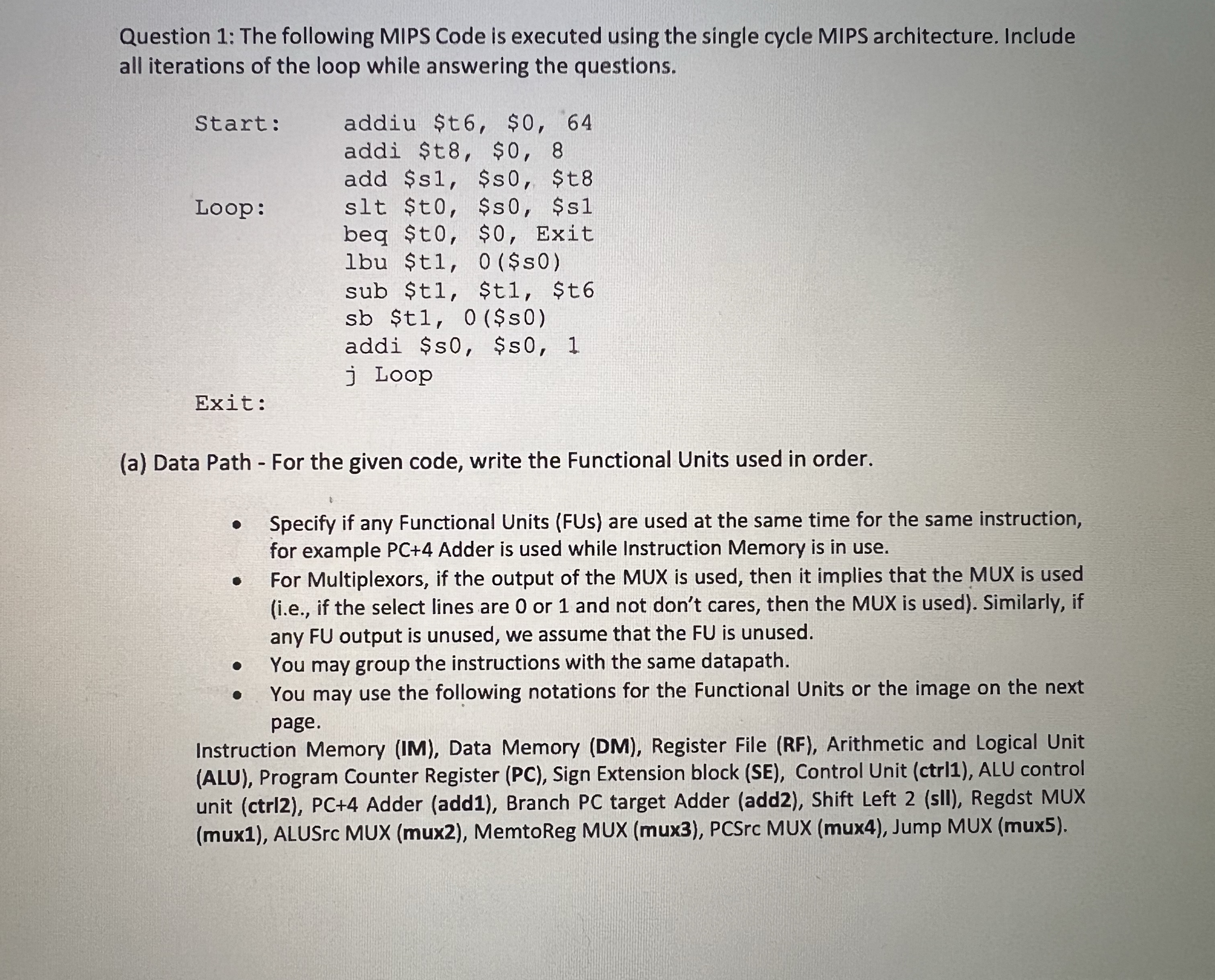
ii Assuming all instructions are executed using a fixed clock cycle length. What is the execution time for the complete codeprogramQuestion : The following MIPS Code is executed using the single cycle MIPS architecture. Include all iterations of the loop while answering the questions.
Start: addiu $t $
addi $t $
add $s $s $t
Loop: slt $t $s $s
beq $ to $ Exit
lbu $t$
sub $t $t $t
sb $t$
addi $s $s
j Loop
Exit:
a Data Path For the given code, write the Functional Units used in order.
Specify if any Functional Units FUs are used at the same time for the same instruction, for example Adder is used while Instruction Memory is in use.
For Multiplexors, if the output of the MUX is used, then it implies that the MUX is used ie if the select lines are or and not don't cares, then the MUX is used Similarly, if any output is unused, we assume that the FU is unused.
You may group the instructions with the same datapath.
You may use the following notations for the Functional Units or the image on the next page.
Instruction Memory IM Data Memory DM Register File RF Arithmetic and Logical Unit ALU Program Counter Register PC Sign Extension block SE Control Unit ctrl ALU control unit ctrl PC Adder add Branch PC target Adder add Shift Left sII Regdst MUX mux ALUSrc MUX mux MemtoReg MUX mux PCSrc MUX mux Jump MUX mux
Question : The following MIPS Code is executed using the single cycle MIPS architecture. Include all iterations of the loop while answering the questions.a Data Path For the given code, write the Functional Units used in order.
Specify if any Functional Units FUs are used at the same time for the same instruction, for example PC Adder is used while Instruction Memory is in use.
For Multiplexors, if the output of the MUX is used, then it implies that the MUX is used ie if the select lines are or and not don't cares, then the MUX is used Similarly, if any output is unused, we assume that the is unused.
You may group the instructions with the same datapath.
You may use the following notations for the Functional Units or the image on the next page.
Instruction Memory IM Data Memory DM Register File RF Arithmetic and Logical Unit ALU Program Counter Register PC Sign Extension block SE Control Unit ctrl ALU control unit ctrl PC Adder add Branch PC target Adder add Shift Left sII Regdst MUX mux ALUSrc MUX mux MemtoReg MUX mux PCSrc MUX mux Jump MUX mux
Step by Step Solution
There are 3 Steps involved in it
1 Expert Approved Answer
Step: 1 Unlock

Question Has Been Solved by an Expert!
Get step-by-step solutions from verified subject matter experts
Step: 2 Unlock
Step: 3 Unlock