

Question: Consider the circuit shown in Fig. 3 and answer following: VDD Inz In 3 Ins Ins Out Fig. 3 i) Find the function implemented
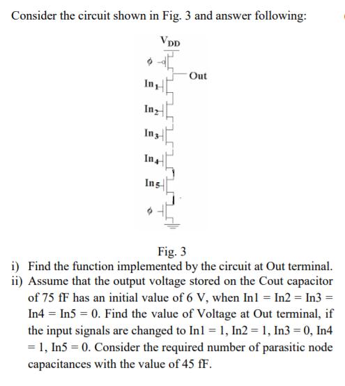
Consider the circuit shown in Fig. 3 and answer following: VDD Inz In 3 Ins Ins Out Fig. 3 i) Find the function implemented by the circuit at Out terminal. ii) Assume that the output voltage stored on the Cout capacitor of 75 ff has an initial value of 6 V, when In1 = In2 = In3 = In4 = In5 = 0. Find the value of Voltage at Out terminal, if the input signals are changed to In1 = 1, In2 = 1, In3 = 0, In4 = 1, In5 =0. Consider the required number of parasitic node capacitances with the value of 45 fF. Consider the circuit shown in Fig. 3 and answer following: VDD Inz In 3 Ins Ins Out Fig. 3 i) Find the function implemented by the circuit at Out terminal. ii) Assume that the output voltage stored on the Cout capacitor of 75 ff has an initial value of 6 V, when In1 = In2 = In3 = In4 = In5 = 0. Find the value of Voltage at Out terminal, if the input signals are changed to In1 = 1, In2 = 1, In3 = 0, In4 = 1, In5 = 0. Consider the required number of parasitic node capacitances with the value of 45 fF.
Step by Step Solution
There are 3 Steps involved in it
Answer The value of the voltage at the out terminal of the circu... View full answer

Get step-by-step solutions from verified subject matter experts