

Question: Consider the Mass-Spring-Damper system shown in Fig. 2 (left), where m is the mass of the cart, k is the spring constant, and b
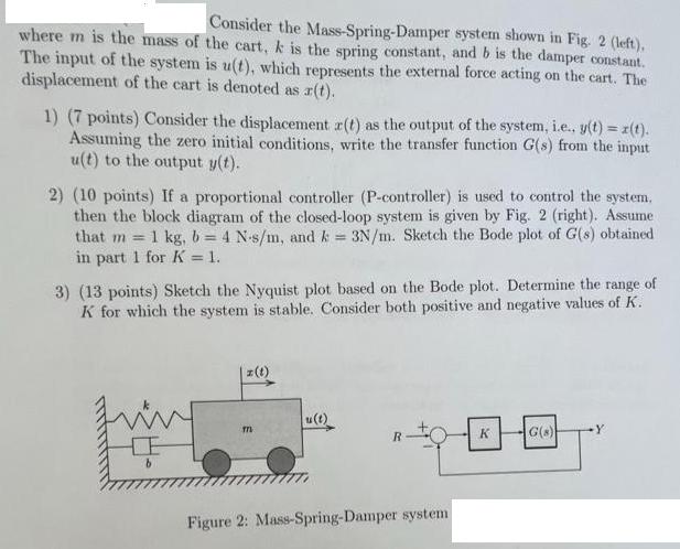
Consider the Mass-Spring-Damper system shown in Fig. 2 (left), where m is the mass of the cart, k is the spring constant, and b is the damper constant. The input of the system is u(t), which represents the external force acting on the cart. The displacement of the cart is denoted as r(t). 1) (7 points) Consider the displacement r(t) as the output of the system, i.e.. y(t) = z(t). Assuming the zero initial conditions, write the transfer function G(s) from the input u(t) to the output y(t). 2) (10 points) If a proportional controller (P-controller) is used to control the system. then the block diagram of the closed-loop system is given by Fig. 2 (right). Assume that m= 1 kg, b = 4 N-s/m, and k = 3N/m. Sketch the Bode plot of G(s) obtained in part 1 for K = 1. 3) (13 points) Sketch the Nyquist plot based on the Bode plot. Determine the range of K for which the system is stable. Consider both positive and negative values of K. m z(t) TTL u(t) R Figure 2: Mass-Spring-Damper system K G(8) Y
Step by Step Solution
3.42 Rating (149 Votes )
There are 3 Steps involved in it

Get step-by-step solutions from verified subject matter experts